CIS117-6 Digital – Microwave and Optical Communications Assignment Sample
Module code and Title: CIS117-6 Digital – Microwave and Optical Communications Assignment Sample
Introduction
This particular report is prepared based on the communication system where in this particular report three specific communication systems are analyzed and those are digital communication, optical communication, and microwave communication, etc. All these three communications systems are analyzed by the author and with the help of Optiwave software and CST software the author tried to accomplish this analysis and achieved their main purpose which is to determine deep knowledge about these three communication systems. In addition, design some of the antennas for better understanding.
Literature Review
According to Foerster et al. 2018, for high-rate remote correspondences, the important measure of unoccupied space in sub-Terahertz frequencies is explored in order to meet the requirements of previous 5G organizations. However, stage clamor severely undermines the presentation of sub-Terahertz frameworks, weakening its advantages. This study, Author examine the concept of automated exchanges tolerant of stage clamor.
The solution to this problem is broken down into three steps: the portrayal of the stage commotion channel, the design of the optimum recipient, and the simplification of the balancing plot. A combined presentation and execution streamlining are suggested in this research. First, Author discuss the strategy behind the demodulation scheme for stage commotion channels and suggests polar measurement, a delicate decision rule for picture recognition.

It has been demonstrated that presentation improvements for both coded and uncoded frameworks are made while the recipient’s degree of complexity significantly reduces. The development of the adjustment conspires for stage commotion is what Author look at next. Author demonstrates that using a celestial body depicted on a cross-section in the sufficiency stage space results in significant performance increases and a low-complexity execution.
The author immediately suggests the use of an efficient double marking and demodulation scheme called Polar-QAM. The offered regulation and demodulation plans provide significant solutions for achieving high-rate correspondences on frameworks that are severely constrained by stage commotion, according to the findings of mathematical reenactment. The system mainly describes the system model.
The system model section mainly gives the proper analysis of the various types of models like the channel model and also the phase model. The algorithm design is also described in that section and also evaluating the various types of algorithm structures for building of the communication structure.
According to Raj, A.B., and Majumder, 2019, from early man’s use of fire signs through the modern day’s space optical correspondences, this overview article discusses developments in remote correspondence. In this survey research, it is discussed how assessments of correspondence advances have changed through time, from ancient Greece to the modern, developed telecom industries.
Law, significance, they cover the development and demonstration of free-space optical (FSO) correspondence technology over a period of many years. The main FSO channel restrictions, the transient and geographical challenges of the FSO correspondence structure, and the techniques for addressing their condition of craftsmanship are introduced. The traditional “quantitative analysis” of the unchanging quality of “FSO” correspondence, improvements in radio over “FSO (RoFSO)”, and combined “FSO/RF” frameworks are also understood.
High-level “developments in FSO” correspondence methods, such as optical free space orthogonal “frequency-division multiplexing (WDM)”, “sub-transporter multiplexing (SCM)”, and “overall interoperability for microwave access (WiMAX)”, “noticeable light interchanges (VLC)”, and “vehicular apparent light correspondences (VVLC)”, are made known. A summary of sophisticated FSO remote earthbound/global organization engineering and deep space optical correspondence frameworks is provided.
Research challenges of FSO frameworks for applications in the Internet of Things or Everything “(IoT/IoE)”, mobile networks, “terahertz range”, quantum correspondence, and submerged optical technologies are described. They highlighted the issues that need to be resolved in upcoming investigations to recognize the FSO correspondence framework’s maximum potential in light of the audit.
The topic mainly describes the various types of concepts like the principle of the “free-space optical” communication, “FSO communication channels”: atmospheric, space, and underwater, and Temporal challenges in the “FSO communication systems” and also describes the spatial mitigation process which can help to improve the communication system and also simplify the process. The paper also gives the proper overview of the communication system and also the change in the system.
This review study introduces the disruptions and advancements of communication technologies during the last several hundred years, starting with the ancient monitors’ fire signs and ending with the modern space optical correspondence. The FSO correspondence innovation’s standards, advantages, and significance are presented. The FSO correspondence framework’s constraints, plan difficulties, and barometric choppiness aggravations are described, along with solutions.
According to Schmidt et al. 2018, advanced communication across great distances should be available through the internet and other means. It offers features like video conferencing that save a tone of time, money, and effort. Only a few years ago, communications technology scared a lot of us, but today it is a part of everyday life for most people.
The repeaters prevent crowding along the route. Using straightforward correspondence frameworks is ludicrous. Depiction of a two-state signal. The contribution to a computerized framework comes in the form of a collection of parts (double or M-exhibit) freedom from bending and impedance Digital correspondence is difficult in that it is less safe for agitation and distortion to be diverted.
It can combine several sign types, including text, audio, and informational signs. Voice communication between people is straightforward compared to electronic information communication on PCs. It is possible to combine both configurations for transmission across a standard media using computerized processes. The methods of encryption and protection are easier to use. The project mainly describes the digital communication system and also develops the idea about the basic elements of digital communication like the transducer, transmitter, and also receiver.
The paper also describes the modes of the communication and also gives information about the methods that are used in the data transmission. So the communication system is mainly the most economical method of communicating through digital means (both internal and external). Because it is less susceptible to noise or distortion and is relatively simple to alter signals, digital communication is always favored over analog communication.
In order to execute complex functionalities, modern digital circuitry is less expensive than analog electronic circuitry. So the paper mainly gives the proper design of digital communication and also develops the idea about the various types of factors that mainly affect the development of digital communication.
According to Jamali et al. 2021, free-space optical (FSO) systems can provide the high information rate, secure, and economically advantageous communication joins required for uses such as distant front-and backhauling for 5G and 6G communication enterprises. Despite the significant advancement of FSO frameworks over the past few years, the requirement of a view link between transmitter and recipient continues to be a major impediment to their organization.
In this study, Author discusses how smart reflecting surfaces (IRSs) could be able to alleviate this requirement. Author explain the optical IRS developments that have already been made, examine optical IRSs with radio-recurrence IRSs and optical transfers, and identify various unresolved concerns for further investigation on IRS-aided FSO correspondences. The file mainly describes the free-space optical communication and also describes the optical reflection surface technology.
The section mainly describes the various type of technology like the mirror-based design, and also the micro mirror. The paper also has Meta-surface-based Designs. The implementation is the section that reflects the Relevant hardware constraints/impairments and also the Verification of the theory. Therefore, they played around with the idea of using optical IRSs to reduce the LoS requirement in FSO correspondence systems.
Author have investigated different optical IRS advances and given them careful consideration with regard to their capabilities, complexities, and operating standards. Additionally, Author has compared two related advancements, namely IRS-aided RF and optical transmission frameworks, with IRS-assisted FSO frameworks. Finally, Author have presented a list of various unresolved examination difficulties pertaining to channel showing, framework design, execution review, and execution advancing future work on IRS-aided FSO frameworks.
According to Sediq et al. 2022, for remote correspondence technology to advance, a strategy for receiving wires for portable devices with improved radiation properties is essential. High information rate, conservatism, productivity, limit, and so forth are extremely important requirements for the original engineering receiving wire. According to the Government Communication Commission, the frequency range of super wideband applications is limited to a range of 3.1–10.6 GHz.
Because super wideband interchanges have been continuously developed to meet the essential requirements of these prototype frameworks, there has been a specialized upheaval in the adjusted radio wiring advancements. This study designed and built a UWB-MIMO radio wire using a CPW-feeder structure and a revolutionary reorganized comma-molded radio wire. By integrating a few circular shapes with curved math formulas, the proposed single monopole receiving wire is designed.
The initial design has a broad impedance data transfer capacity between 2.469 and 14.203 GHz. The intended unit cell’s components measure 21 millimeters by 16 millimeters (0.172 L by 0.131 L), and double symmetric radio wires are typically 21 millimeters by 34 millimeters by one millimeter in size. Next, 2 X 2 Multiple Input Multiple Output (MIMO) radio cables are planned using this reduced radio wire. Two comparison calculations are set with a T-molded decoupling structure in the proposed low-profile MIMO radio wire.
According to estimation results, the MIMO radio wire exhibits a wide range of measurements, including low-esteem common coupling properties, better channel limit errors of under 0.29 bits/s/Hz, envelope connection coefficients more modest than 0.004 by a large margin field radiation, all-out dynamic reflection coefficients under 10 dB, variety gains of under 9.98 dB, and OK mean powerful increases (MEG 0.5, MEGratio = 1). At a working frequency of 13.4 GHz, the suggested receiving wire has a maximum peak gain value of 6.18 dBi. So the paper mainly describes the process of microwave communication.
According to Shi 2018, microwave mixers are used in electromagnetic and centimeter devices including radar, satellite imagery, and telecommunication networks. It is being used to execute spectrum up or down conversion, that involves converting an intermediary frequencies information towards the radio waves region or converting a Radio wave towards the IF spectrum.
Microwave waveguide processors provide a broad operational bandwidth, strong separation, adaptability and reusability, and narrow bandwidth when opposed to older broadband integrators. MWP integrators have already been shown using a variety of architectures, including spiraled mechanisms, concurrent ocular stimulators, a photonic integrated synthesizer, and so on. The standard cumulated architecture suffers from significant combining peaks and conversions inefficiency.
These issues may be solved by using concurrent architecture. However, in concurrent constructions, the light beam width variation branches are unstable and dangerous, affecting the mixer’s effectiveness. Furthermore, using two mechanisms of action makes the device heavy and complex. As a result, a WMP sound system with an incorporated synthesizer is desirable. Earlier frequency selective blender research only achieved human combining. More sophisticated spectrum integrators, like in (I/Q) combining, symmetrical melding, and photo avoidance combining, are sought.
I/Q mixers, in particular, are beneficial for I/Q analog and digital and may be used in minimal IF emitters; unbalanced mixers can eliminate ac signals and increase converter effectiveness; and image avoidance mixers can decrease undesirable image carrier frequency. A technology that performs all of the foregoing duties simplifies the design and expense of a data transmission, and is therefore sought in industrial applications.
Throughout this arrangement, unfortunately, harmonic up-conversion isn’t really conceivable. Furthermore, both integrators used an enhanced optical passband with a finite bounce frequency, which constrained the working spectrum of the machines. Additionally, the blender has the opportunity to turn among speed and descending modes. The suggested programmable blender has advantages in infrared and wideband micro strip antennas due to its easy and large operational spectrum.
Section-1: Digital Communication
- a)
Entropy: In digital communication specifically entropy refers to the rate of randomness. If the entropy is higher than the signaling error is much more frequent. The direct relationship of entropy and the attainable data speed is present, meaning if the entropy is increased then maximum attainability speed also increases (Wang et al. 2019). This is also directly proportional with noise as well as bandwidth. In addition, entropy of any signal is inversely proportional with compressibility. Means, if the value of entropy is increased then the factor’s compression is smaller.
Arithmetic Expression:
If the mean value is l(xi) for the alphabet source of X where the m different icons are represented via H(X).
Then, log [AB] = log A + log B
Equations:
H(X) is called entropy of X which is a measure of average data content for each source symbol or icon. If the users are considered H(X) as an average amount of source entropy in the case of uncertainty for source X then the users are able to resolve this with the help of the alphabet. So the formula for the binary source is H(X) = log2 log2 = 1b/symbol and the lower as well as upper bound of entropy is 0 £ H(X) £ log2m.
These mathematical expressions are used to calculate the entropy in the digital communication system.
- b) Digital Communication Block Diagram: In the figure below the author is trying to show all the key components of the digital communication system.
The vital parts of a computerized correspondence framework are: “ Input source, Source coder, Channel coder, Baseband processor, channel, band pass demodulator, channel decoder, source decoder, output signal.”
Input Source
Information or data sources are by and large simple, for example, sound and video signals. These signs are non-electrical amounts and can’t be handled straight by a computerized correspondence framework.
Source Encoder
The source encoder is utilized to pack the information to the base number of pieces. This aids in the successful utilization of transmission capacity. Eliminates zero excess pieces or pointless additional pieces from the info information.
Channel encoder
The channel encoder is performing mistake adjustment encoding. During signal transmission, clamor in the channel can change the sign. Subsequently, the channel encoder gives repetitive pieces in the message information to give blunder free information on the receiving side.
Base-band Processor
Low-speed remote transmission, baseband sign can be communicated straightforwardly. Be that as it may, on the off chance that the user wants to send their information in a loud air. The user really wants to apply elements, for example, beat molding and line coding. This assignment is performed by the baseband processor (Pietroni et al. 2019). For rapid transmissions, advanced information is currently tweaked utilizing high recurrence transporters, similarly as with simple transmissions. The baseband modulator assumes control over this errand.
Channel
A correspondence channel is a medium through which a sign is sent from the shipper to the beneficiary. This is important for the model where most extreme commotion is added to the sign.
Base-band Decoder
Baseband decoders are utilized to reestablish the first information from beat or line encoded information.
Channel Decoder
The channel decoder plays out some mistake rectification in the wake of perceiving the arrangement. The sign might be misshaped during transmission. This is fixed by adding excess pieces to the sign. Adding this piece serves to reestablish the first sign totally.
Source Decoder
The subsequent signal is digitized again by examining and quantization, bringing about an unadulterated computerized yield without loss of data. The source decoder reestablishes the source yield.
Output Signal
This is the result that was created after the whole cycle. This is the end of the digitalization process and the users are able to get their required result after this process end.
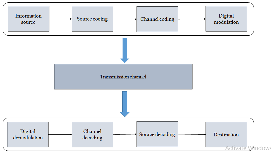 Figure 1: Key Components of Digital Communication System (Source: Provided)
- a) Digital Modulation: Digital to analog conversion is particularly known as digital modulation method or technique. Digital modulation helps the users to understand their data or information in a better way meaning it offers better data capacity, easy system availability, then high data protection and high quality communication (Maddah-Ali et al. 2022). Meaning, digital modulation methods have a very high demand for their data convey volume as well as for their data capacity compared to the” analog modulation technique”. Several digital modulation techniques are available like ASK, FSK, and PSK, etc. But all these techniques are used in real as per user’s demands or requirements of the task.
- b) Three Modulation Techniques: Many modulation techniques are available among those three essential techniques are ASK, FSK and PSK. These modulations are discussed in the below section. In the case of ASK if the degree of freedom is 1 then it states that the modulation depth is almost accurate means 100% correct. The same is happening for FSK and PSK modulation.
ASK – Full form of ASK is Amplitude shift Keying. In this particular modulation the output depends on the input information and based on the input the result determines that that should be on the zero level or the result varies in between positive as we all in negative level. But this depends on the carrier frequency.
FSK – Full form of FSK is Frequency shift Keying. In this modulation output signal’s frequency is high or low, but this also depends on the applied input data.
PSK – Full form of PSK is Phase shift Keying. This modulation is classified within three parts BPSK (“Binary Phase shift Keying”), QPSK (“Quadrature Phase shift Keying”), and DPSK (“Differential Phase shift Keying”) (Jahani-Nezhad et al. 2022). QPSK changes as per the amount of phase shift and DPSK changes the phase as per the previous or past value.
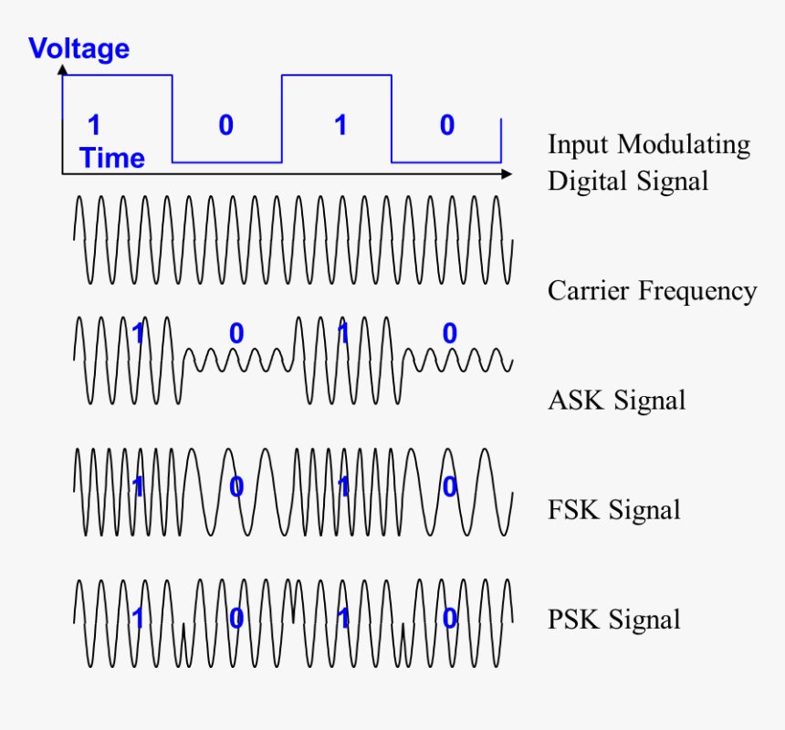 Figure 2: An example of ASK, PSK and FSK Digital Modulation (Source: https://www.kindpng.net)
- DMS Software:
- a) Huffman Code
Alphabet = { a, b, c, d, e, f, g, h}
Probabilities = {0.05, 0.1, 0.25, 0.02, 0.25, 0.03, 0.25, 0.05}
| Alphabet | Probability | Huffman Code |
| a | 0.05 | 111 |
| b | 0.1 | 01 |
| c | 0.25 | 0 |
| d | 0.02 | 1100 |
| e | 0.25 | 0 |
| f | 0.03 | 1101 |
| g | 0.25 | 0 |
| h | 0.05 | 110 |
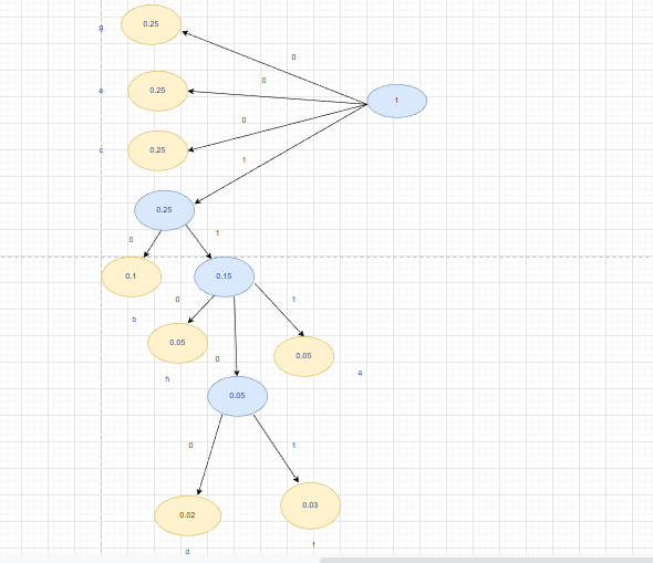 Figure 3: Huffman Tree (Source: Self-created in Draw.io)
- b) Average Length
| Alphabet | Probability | Huffman Code | Total Number of Bits |
| a | 0.05 | 111 | 3 |
| b | 0.1 | 01 | 2 |
| c | 0.25 | 0 | 1 |
| d | 0.02 | 1100 | 4 |
| e | 0.25 | 0 | 1 |
| f | 0.03 | 1101 | 4 |
| g | 0.25 | 0 | 1 |
| h | 0.05 | 110 | 3 |
Average Length = Σ PiNi (3.25)
Therefore,
Average Length = (0.05*3+0.1*2+0.25*1+0.02*4+0.25*1+0.03*4+0.25*1+0.05*3)
Average Length = 3.25 bits/ symbol.
- c) Efficiency of Huffman Code
Efficiency = H(X) / L ………………(i)
Where,
L = 3.25 bits/ symbol.
And,
H(X) = – Σ Pi log2 Pi
So,
H(X) = –Palog2 Pa – Pb log2 Pb – Pc log2 Pc – Pd log2Pd – Pe log2 Pe – Pf log2 Pf – Pg log2 Pg – Ph log2 Ph
H(X) = – 0.05 log2 0.05 – 0.1 log2 0.1 – 0.25 log2 0.25 – 0.02 log2 0.02 – 0.25 log2 0.25 – 0.03 log2 0.03 – 0.25 log2 0.25 – 0.05 log2 0.05
H(X) = 0.216 + 0.332 + 0.5 + 0.113 + 0.5 + 0.152 + 0.5 + 0.216
H(X) = 2.529
Therefore,
From equation (i),
Efficiency = H(X) / L
Efficiency = 2.529 / 3.25
Efficiency = 0.778
So, Efficiency = 77.82 %
- Shannon-Fano Code
Alphabet = { a, b, c, d, e, f }
Probabilities = { 0.4, 0.3, 0.15, 0.1, 0.03, 0.02 }
| Alphabet | Probability | Stage 1 | Stage 2 | Stage 3 | Stage 4 | Shannon-Fano Code | Length |
| a | 0.4 | 0 | 0 | 00 | 2 | ||
| b | 0.3 | 0 | 1 | 01 | 2 | ||
| c | 0.15 | 1 | 0 | 10 | 2 | ||
| d | 0.1 | 1 | 1 | 0 | 110 | 3 | |
| e | 0.03 | 1 | 1 | 1 | 0 | 1110 | 4 |
| f | 0.02 | 1 | 1 | 1 | 1 | 1111 | 4 |
Figure 4: Shannon-Fano Code Tree in the Table format (Source: Self-created)
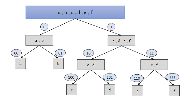 Figure: Shannon-Fano Tree (Source: Provided)
The author prepares the Shannon-Fano code tree, where at first they arrange the probabilities in descending order and after that select the first two alphabets of probability, where the sum of those two are divided with rest ones. Also the author provides 0 for upper values and 1 for lower values. The same process is performed again and again until all the probabilities are examined.
Section-2: Microwave Communication
The ISM band range is 2.45 GHz.
The resonance frequency for this particular antenna is f = 2.45 GHz +(051/2) MHz
Therefore, f = 2.45 GHz + 25.5 MHz
So, f = 2.45 GHz + 0.0255 GHz
So, f = 2.48 GHz
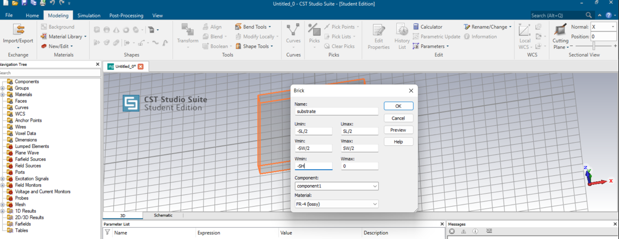 Figure 5: First Stage WLAN Antenna Implementation Configuration (Source: Self-Created on CTS Studio Suite)
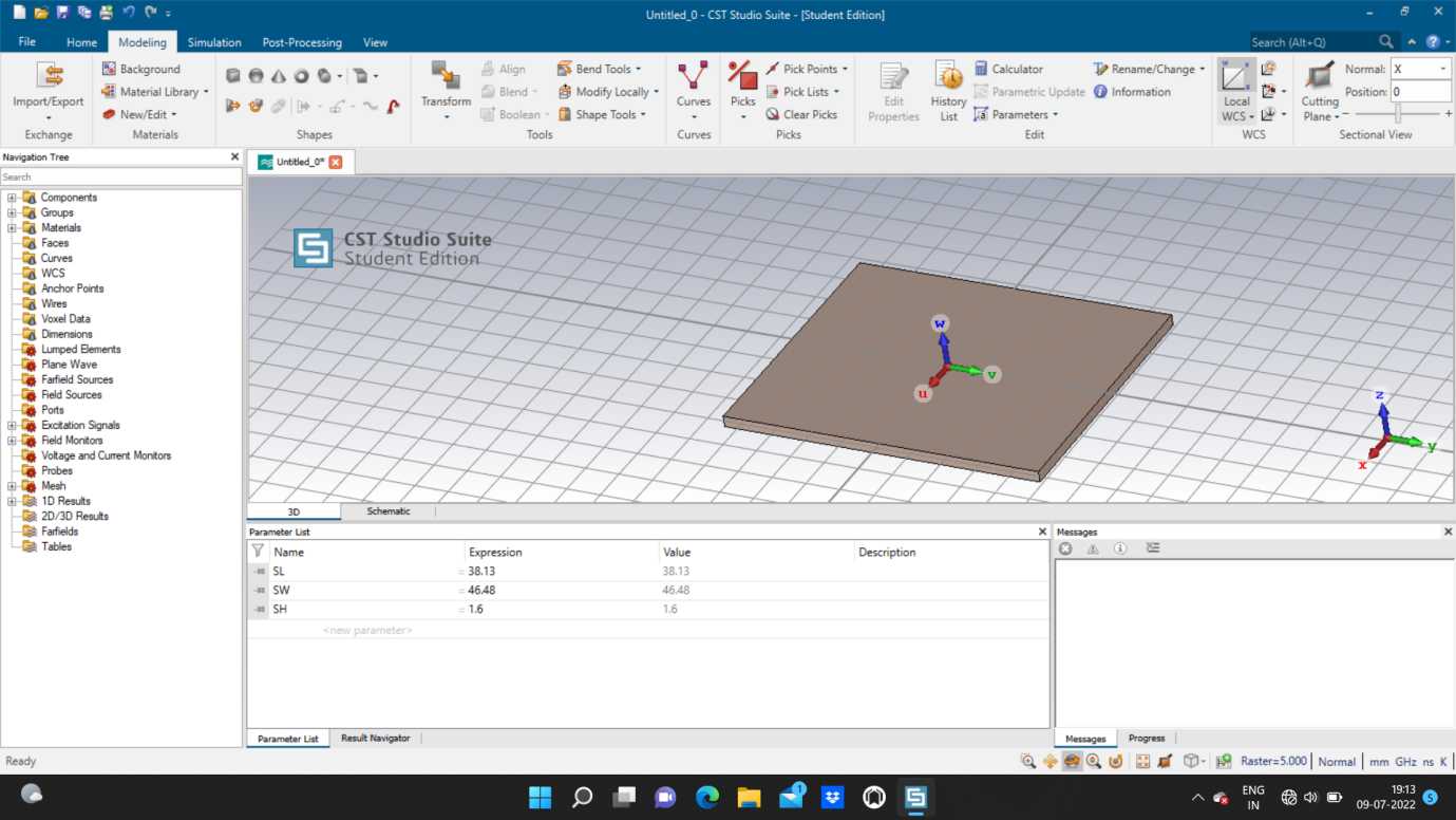 Figure 6: First Stage of WLAN Antenna Implementation (Source: Self-Created on CTS Studio Suite)
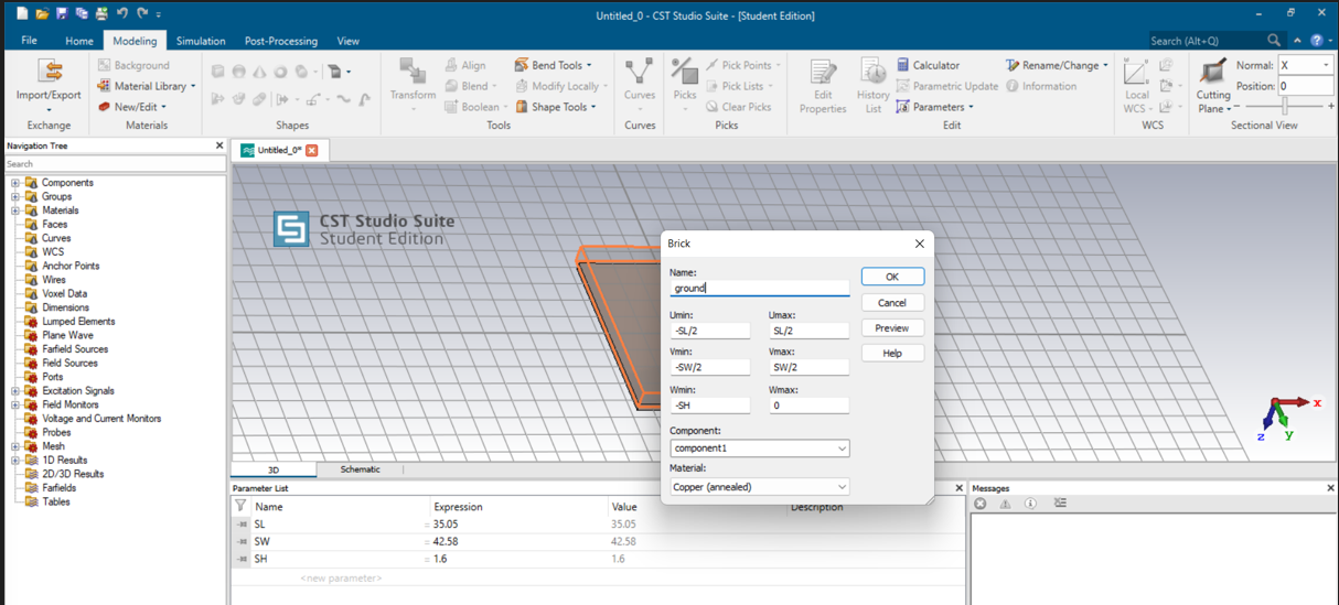 Figure 7: Second Stage of WLAN Antenna Implementation Configuration (Source: Self-Created on CTS Studio Suite)
 Figure 8: Second Stage of WLAN Antenna Implementation (Source: Self-Created on CTS Studio Suite)
 Figure 9: Third Stage of WLAN Antenna Implementation (Source: Self-Created on CTS Studio Suite)
 Figure 10: Fourth Stage of WLAN Antenna Implementation (Source: Self-Created on CTS Studio Suite)
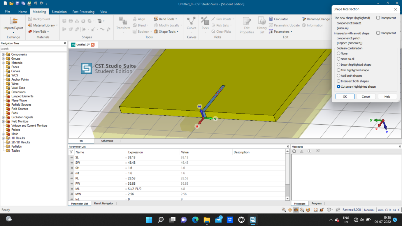 Figure 11: Fifth Stage of WLAN Antenna Implementation (Source: Self-Created on CTS Studio Suite)
 Figure 12: Final Structure of WLAN Antenna (Source: Self-Created on CTS Studio Suite)
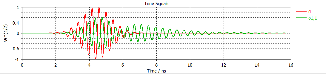 Figure 13: Port Signals (Source: Self-Created on CTS Studio Suite)
The port signal offers individuals the i1 and 01, 1 based on the provided port while respective to the time. If there is a strong signal present then the port signal should begin at zero, and then after that it should move towards zero again.
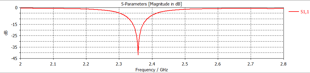 Figure 14: S-Parameters (Source: Self-Created on CTS Studio Suite)
This is known as a patch antenna along with its ground surface that is defected. The ideal value of the antenna should be 1300 GHz. The s-parameter can also be defined as magnitude present in db.
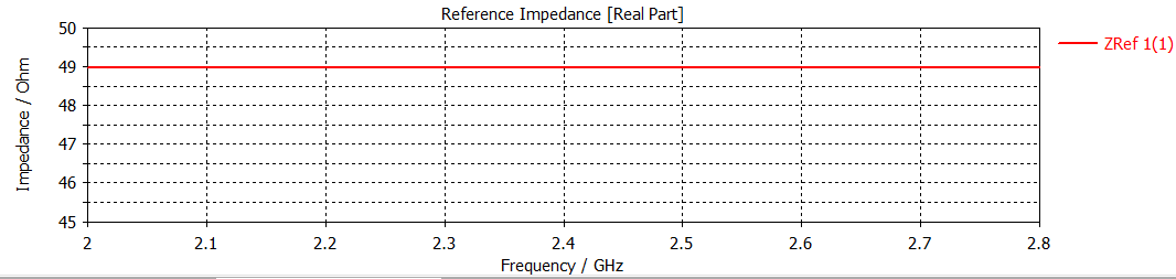 Figure 15: Reference Impedance (Source: Self-Created on CTS Studio Suite)
This number can also present the s-parameters, if there is a s-parameter generated then it is crucial to present the information on currents and voltages. The ZRef(1) is the variable name and the frequency is linear.
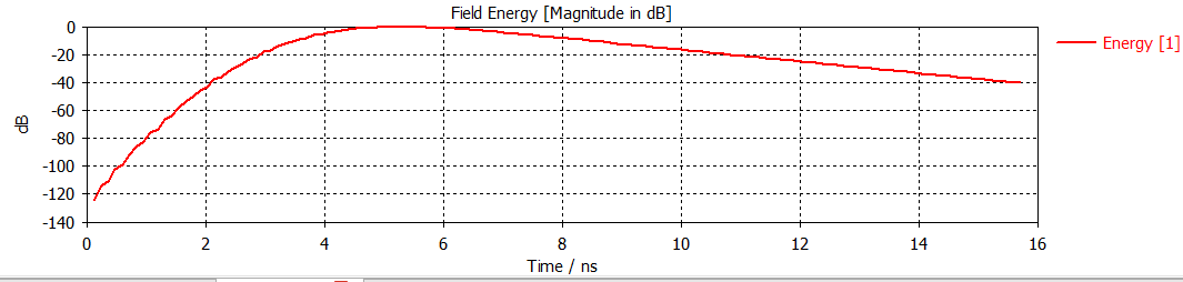 Figure 16: Energy (Source: Self-Created on CTS Studio Suite)
The field energy represents the overall energy consumption of the waves and signals. The frequency of energy will start from the level -120 and it will reach the level 0 and then slowly decrease to -40.
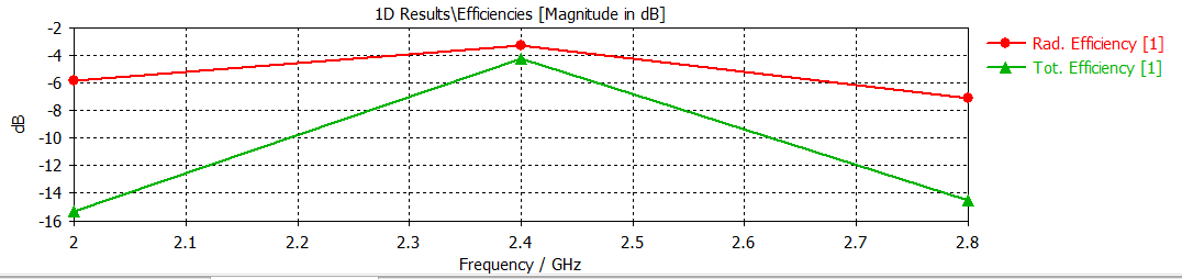 Figure 17: Efficiencies (Source: Self-Created on CTS Studio Suite)
The efficiency of signal selection that is present inside the signal region is called a function of the mass that is produced. The red one is known as radiation efficiency and can also be represented as a crucial parameter to present the efficiency of the antenna that receives and transmits the RF signals. The total efficiency is presented as an inverter for different levels of DC voltage.
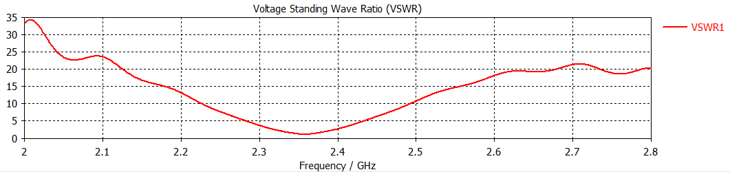 Figure 18: VSWR (Source: Self-Created on CTS Studio Suite)
The VSWR can also be called voltage standing wave ratio and the frequency is constantly fluctuating. Starting from the upper range to the lower range it will constantly move.
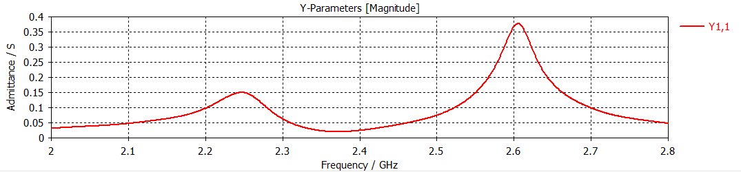 Figure 19: Y Matrix (Source: Self-Created on CTS Studio Suite)
The Y-parameter will be presented as magnitude and the variable name will be presented as Y1,1. The y axis is presented as frequency. And this will also stay at the lower range of frequency and slowly will rise in the upper range.
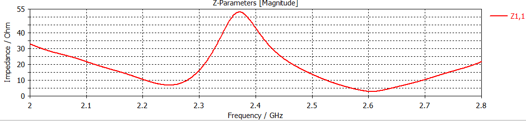 Figure 20: X Matrix (Source: Self-Created on CTS Studio Suite)
The Z-parameter will be presented with the help of magnitude, and it will be called Z1,1. The X axis here is also presented as frequency and it will start from the upper level to the lower level, and it will again reach the upper range.
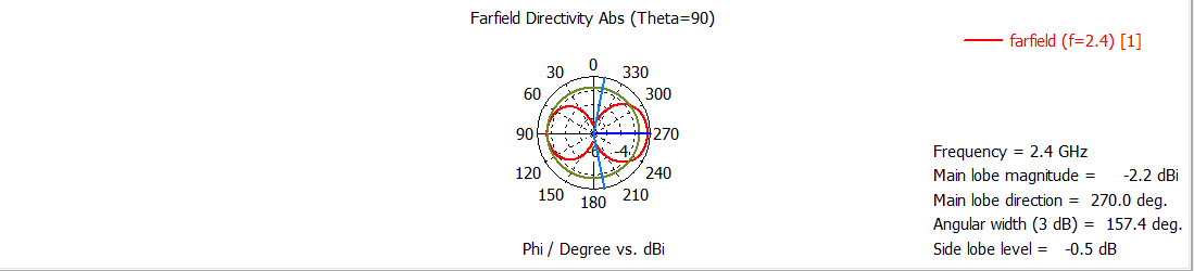 Figure 21: Fairfield 2.4 GHz (Source: Self-Created on CTS Studio Suite)
The Fairfield directivity will generate the value 2.4 GHz, The main lobe magnitude is -2.2 dBi. The main lobe direction is 270.0 deg. The angular width is 157.4 deg. And the side lobe level is -0.5 dB.
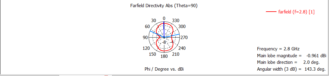 Figure 22: Fairfield 2.8 GHz (Source: Self-Created on CTS Studio Suite)
The frequency value of Fairfield is 2.8 GHz, and the main lobe magnitude is -0.961 dBi, main lobe magnitude value is 2.0 deg and the angular value is 143.3 deg.
 Figure 23: Excitation (Source: Self-Created on CTS Studio Suite)
The process of generating electromagnetic energy is known as Excitation. The charged particles and their movement will be observed in both the axes.
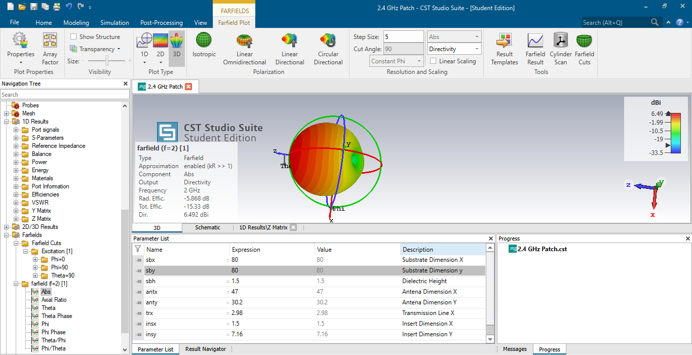 Figure 24: Abs (Source: Self-Created on CTS Studio Suite)
Here all the axis are presented in the color green, red and blue and the red is the maximum dBi and the blue is the minimum dBi.
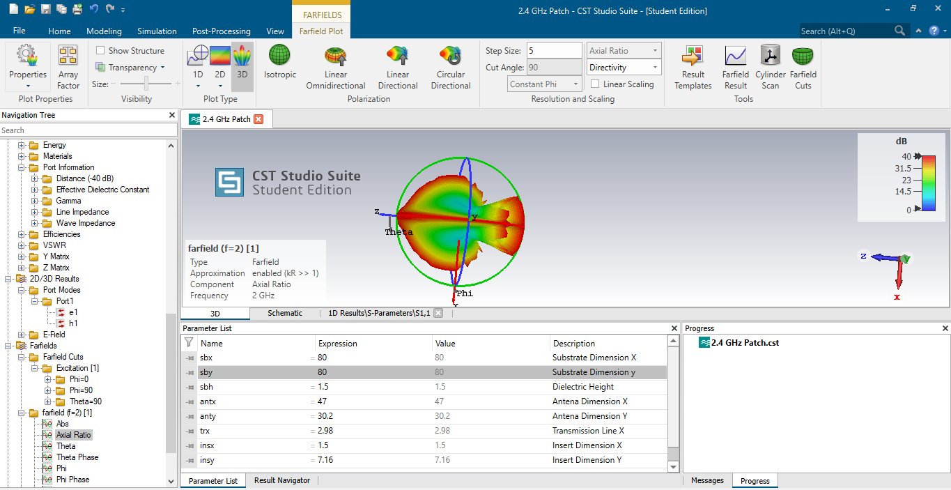 Figure 25: Axial Ratio (Source: Self Created on CTS Studio Suite)
The Axial ratio will be presented with the help of three axes and the type is known as fairfield. The components are named as axial ratio and the frequency here is 2GHz.
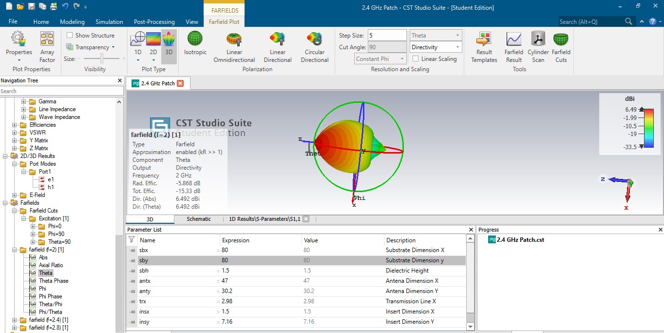 Figure 26: Theta (Source: Self Created on CTS Studio Suite)
The components here are theta, the frequency value is 2 GHz and the output is directivity.
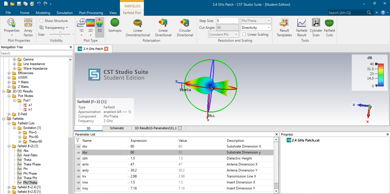 Figure 27: Phi/Theta (Source: Self Created on CTS Studio Suite)
The component name here is phi/theta and the frequency value is 2 GHz.
Section-3: Optical Communication
- a) The ONU number in every floor is 20, this can be measured as the capability of ONU while accessing the network to voice, and video that is installed in every room. While utilizing the WDM method, there are a total of 40 channels implemented with the optical transmitter. The main motive behind the strategy is to save the expenses of installation for several fiber cables. With the help of fiber cable link multiple channels can be assigned together.
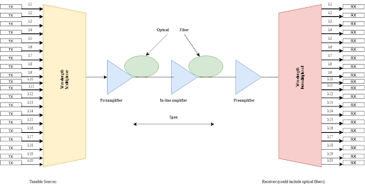 Figure 20: Block Diagram of Radio-over-Fiber System (Source: Self-Created in Draw.io)
- b)
Budget of the Design
| Parameter | Value |
| Operating Wavelength | 1550 nm |
| Maximum Output Optical Power | 7.00 dBm |
| Minimum Receiver Sensitivity | -28 dBm |
| Optical Fiber Type | Single Mode |
| Fiber Optic Span | 50 km |
| Attenuation | 0.22 dB/km |
| Number of output ports | 20 Channels |
| Frequency Spacing | 100 GHz |
| Optical Transmit Power | 7 dB |
| Extinction Ratio | 30 dB |
| Modulation Type | RZ |
| Numbers of connectors | 4 |
| Splice loss | 0.1dB |
| Connector loss | 0.75dB |
| Safety margin | 3.0dB |
Budget = [fiber length (km) × fiber attenuation per km] + [splice loss × number of splices] +[connector loss × number
of connectors] + [safety margin]
Therefore,
Budget = [ 50 km * 0.22 dB/Km] + [ 0.1 dB * 4] + [ 0.75dB * 4] + [ 3.0 dB]
Budget = 17.4 dB
- c) Implementation of Radio Over Fiber System in Optiwave Software
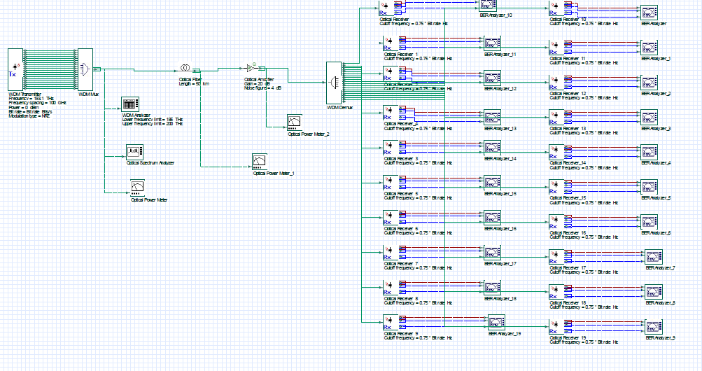 Figure 21: A WDM Fiber Communication with 20 Channels (Source: Self created in Optiwave)
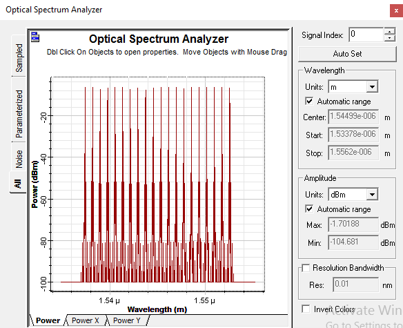 Figure 22: Output of Optical Spectrum Analyzer (Source: Self created in Optiwave)
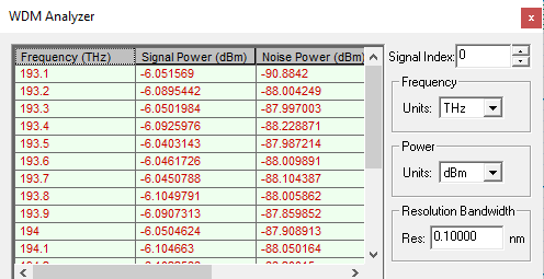 Figure 23: Result of WDM Analyzer with respect to Optical Multiplexer (Source: Self created in Optiwave)
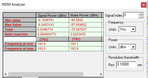 Figure 24: Summary of WDM Analyzer (Source: Self created in Optiwave)
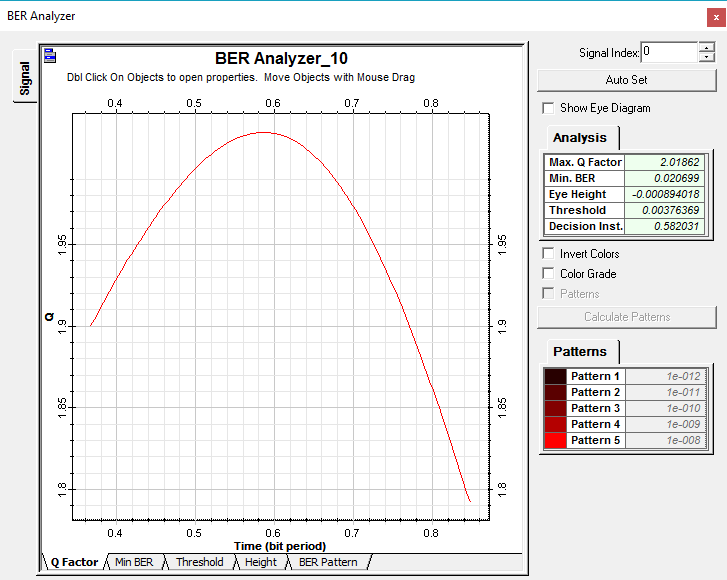 Figure 25: Q factor Curve for Channel 1(Source: Self created in Optiwave)
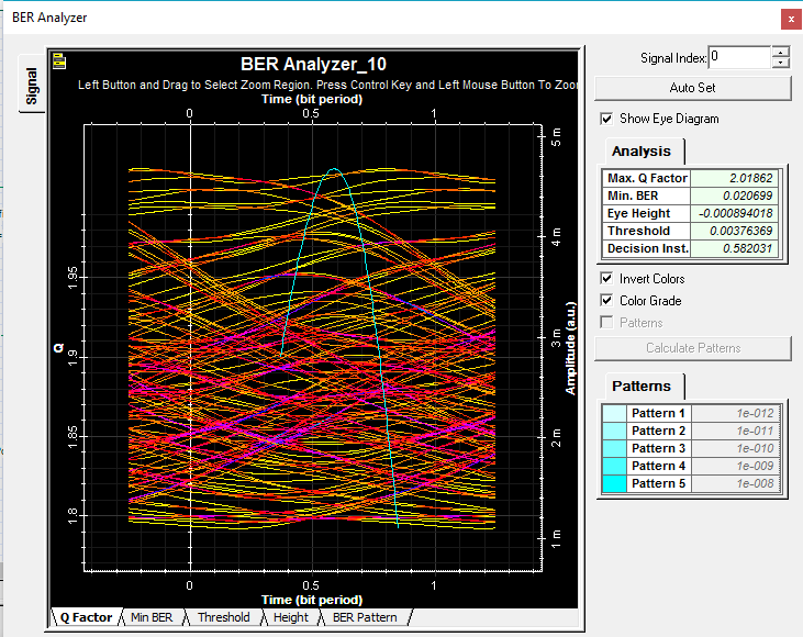 Figure 26: Eye Curve for Channel 1(Source: Self created in Optiwave)
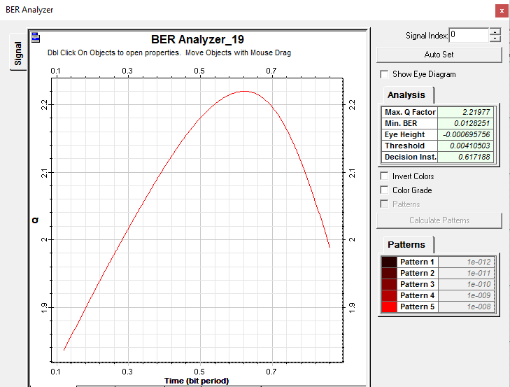 Figure 27: Q factor Curve for Channel 9 (Source: Self created in Optiwave)
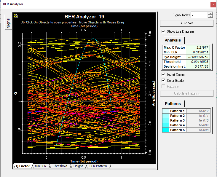 Figure 28: Eye Curve for Channel 9(Source: Self created in Optiwave)
d)
Comparison
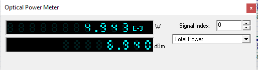 Figure 29: Result of Input Power for Optical Multiplexer (Source: Self created in Optiwave)
 Figure 30: Result of Output Power for Optical Demultiplexer (Source: Self created in Optiwave)
With the help of above results the author clearly shows that the input power of the signals is much lesser than the output signals. Meaning after demux the strength of the data transfer is increased.
e)
Number of Channels
∆ f = ∆ λ / λ^2* C
∆ f = ( (0.8 * 10^-9) / (1550 * 10^-9) * (1550 * 10^-9) ) * (3 * 10 ^8)
∆ f ≈ ( 9.99 * 10^10) Channels
Conclusion
After complete analysis the author understands that digital communication defines the physical data transfer via “point to point” otherwise “point to multipoint” interaction or communication channels. Digital communication is now an important aspect of everyone’s life. With the help of digital communication the users are able to transfer discrete messages and in this particular communication system the data transmission depends on the characteristics of the data.
In the case of microwave communication all the data or information is transferred by electromagnetic waves. Microwaves are particularly used in “point to point” communication. However, their narrow wavelengths permit “conveniently-sized antennas” that direct them within small beams, and it is directly pointed in the receiving antenna.
Along with this in the case of optical communication, light is their data transferring media and it is used to cover long distances and the users are performed the task with the help of visual applications or by electronic devices. In this analysis the author determines several visual results and determines all three communication systems performance. At the end of the analysis the author states that all the purpose of this analysis is successfully achieved.
Reference List
Journals
Flew, T. and Wilding, D., 2021. The turn to regulation in digital communication: the ACCC’s digital platforms inquiry and Australian media policy. Media, Culture & Society, 43(1), pp.48-65.
Flew, T., 2019. Digital communication, the crisis of trust, and the post-global. Communication Research and Practice, 5(1), pp.4-22.
Flew, T., Martin, F. and Suzor, N., 2019. Internet regulation as media policy: Rethinking the question of digital communication platform governance. Journal of Digital Media & Policy, 10(1), pp.33-50.
Foerster, M., Thielens, A., Joseph, W., Eeftens, M. and Röösli, M., 2018. A prospective cohort study of adolescents’ memory performance and individual brain dose of microwave radiation from wireless communication. Environmental health perspectives, 126(7), p.077007.
Gandasari, D. and Dwidienawati, D., 2020. Evaluation of Online learning with Digital Communication media during the Covid 19 Pandemic. Journal of the Social Sciences, 48(3).
Gong, C., Wu, S., Zuo, C., Yang, K., Li, S., Zhang, J., Dai, Z., Huang, M., Zhao, M., Ni, R. and Xu, Z., 2021. Microwave Communication Under Weak Intensity to Quantumized Level: Recent Progress and Future Challenges. Journal of Communications and Information Networks, 6(1), pp.17-31.
Hesmondhalgh, D., 2019. Have digital communication technologies democratized the media industries?.
Jahani-Nezhad, T., Maddah-Ali, M.A., Li, S. and Caire, G., 2022. SwiftAgg+: Achieving Asymptotically Optimal Communication Load in Secure Aggregation for Federated Learning. arXiv preprint arXiv:2203.13060.
Kobayashi, M., Caire, G. and Kramer, G., 2018, June. Joint state sensing and communication: Optimal tradeoff for a memoryless case. In 2018 IEEE International Symposium on Information Theory (ISIT) (pp. 111-115). IEEE.
Lai, Y., Su, H., Wang, G., Tang, X., Liang, X., Huang, X., Li, Y., Zhang, H., Ye, C. and Wang, X.R., 2019. Improved microwave dielectric properties of CaMgSi2O6 ceramics through CuO doping. Journal of Alloys and Compounds, 772, pp.40-48.
Mandal, D., Shah, N. and Woodruff, D.P., 2020, July. Optimal communication-distortion tradeoff in voting. In Proceedings of the 21st ACM Conference on Economics and Computation (pp. 795-813).
Meyer, D.H., Cox, K.C., Fatemi, F.K. and Kunz, P.D., 2018. Digital communication with Rydberg atoms and amplitude-modulated microwave fields. Applied Physics Letters, 112(21), p.211108.
Pietroni, E., 2019. Experience design, virtual reality and media hybridization for the digital communication inside museums. Applied System Innovation, 2(4), p.35.
Pokrovskaia, N.N., Leontyeva, V.L., Ababkova, M.Y., Cappelli, L. and D’Ascenzo, F., 2021. Digital communication tools and knowledge creation processes for enriched intellectual outcome—experience of short-term E-learning courses during pandemic. Future Internet, 13(2), p.43.
Qaisar, Z.H., Irfan, M., Ali, T., Ahmad, A., Ali, G., Glowacz, A., Glowacz, W., Caesarendra, W., Mashraqi, A.M., Draz, U. and Hussain, S., 2020. Effective beamforming technique amid optimal value for wireless communication. Electronics, 9(11), p.1869.
Shi, C., Wang, F., Sellathurai, M., Zhou, J. and Salous, S., 2019. Low probability of intercept-based optimal power allocation scheme for an integrated multistatic radar and communication system. IEEE Systems Journal, 14(1), pp.983-994.
Stone, C.B. and Wang, Q., 2019. From conversations to digital communication: The mnemonic consequences of consuming and producing information via social media. Topics in cognitive science, 11(4), pp.774-793.
Sun, Y., Zhang, L., Feng, G., Yang, B., Cao, B. and Imran, M.A., 2019. Blockchain-enabled wireless Internet of Things: Performance analysis and optimal communication node deployment. IEEE Internet of Things Journal, 6(3), pp.5791-5802.
Uijlenhoet, R., Overeem, A. and Leijnse, H., 2018. Opportunistic remote sensing of rainfall using microwave links from cellular communication networks. Wiley Interdisciplinary Reviews: Water, 5(4), p.e1289.
Wahyudin, A. and Hikmaturokhman, A., 2021. Analysis of Cross-Ocean Microwave Communication Systems Using Point-To-Point, Space Diversity and Hybrid Diversity Configurations. J. Commun., 16(8), pp.331-340.
Wang, Y., Hu, J., Chen, X. and Wang, L., 2019. Distributed bandit learning: Near-optimal regret with efficient communication. arXiv preprint arXiv:1904.06309.
Know more about UniqueSubmission’s other writing services:
