
COMPUTATIONAL FLUID DYNAMICS FOR ENGINEERING APPLICATIONS
Abstract
The following report is based on a numerical aerodynamic simulation of a “box-type trailer”. The objective of the simulation is to find out what type of flow effects result from the motion of the trailer at approximately 50mph. The results showed that the trailer did not perform very well.
The performance of the trailer improved with the use of some modifications such as deflector and teardrop trailer. However, there is still room for more experimentation with reduction of frontal thrust force and the study on the aerodynamics of the tire.

The technique of CFD (or “Computational Fluid Dynamics”) applies to the problem of solving the 3D “Navier-Stokes equation”. In the absence of mathematical methods of solving the 3D form of NS equation, solutions require numerical computations. CFD tools, for example, ANSYS, are widely used in engineering businesses that manufacture automobiles.
The automobile manufacturers use CFD because they are interested in the drag and lift coefficients that their vehicles encounter as air flows past it. An efficient aerodynamic car has a small pull and lifts coefficient. The advantage is that the vehicle consumes less fuel and is quicker.
Commercial vehicles like trucks and lorries are used to transport products from one place to another. As the number of cars and automobiles on the road has increased tremendously in the last two decades, there has been a very sharp rise in the “carbon-dioxide levels” present in the atmosphere.
This is highly damaging for the environment which is not ready to recycle such a very high amount of carbon from the atmosphere. Therefore to reduce the impact of “Internal combustion engine” vehicles on the environment, manufacturers have started to focus on the aerodynamics of their vehicle.
The need to reduce the fuel consumption of the vehicles produced in the automotive sector has led to many companies focussing on CFD analysis software to calculate “lift and drag forces” on commercial vehicles. Minimizing these two forces on any vehicle can lead to a lot of savings for the vehicle owner in terms of fuel costs.
This also has a positive effect on the environment. The commercial vehicles are not designed for performance, and hence they are aerodynamically inefficient. Therefore, reducing the aerodynamic forces on commercial vehicles is necessary to reduce fuel consumption and environmental damage.
Some of the modifications that are fitted into commercial trucks to reduce the drag force that they encounter are “deflector”, “gap fairing”, “vortex stabilizer”, “frame extension” and “teardrop”.
Table 1: Devices for the “truck-trailer” modification
(Source: http://i-rep.emu.edu.tr:8080/jspui/bitstream/11129/4160/1/shirihamidreza.pdf)
The aerodynamic forces can change with the speed of the truck because the flow regime changes as the “Reynold’s number” changes. “Lift and drag” both are dependent only on the geometry of solid and the fluid velocity. These two factors are used to determine the aerodynamic forces acting on the body.
In the works done by (Shiri, 2016), the authors conducted experiments into the methods of reducing the drag on commercial vehicles. The tests were led into the aerodynamic behaviour of a tipper truck. The assumptions for the analysis was that the velocity of the air is 90kmph, and the yaw angle is 0-degree.
The results of the experiments showed that the “frame extension” and the “deflector” showed the maximum reduction in the value of the drag coefficient. In a standard box type trailer, the gap between the pilot cabin and the trailer is an area that is highly susceptible to aerodynamic drag.
In the research conducted by (Shiri, 2016, ii) it was observed that the model showed a “drag reduction” of 39% with a “top fillet edge” and a 42% “reduction in drag coefficient” when a combination of frame extension with deflector was used.
The results of this study are highly relevant because the construction of the tipper is not very different from the box-trailer. The essential steps for conducting a CFD analysis are the modelling of the solid geometry and setting the conditions on the boundaries of the solid.
Table 2: The boundary conditions used in the CFD simulation
(Source: http://i-rep.emu.edu.tr:8080/jspui/bitstream/11129/4160/1/shirihamidreza.pdf)
Among the different methods to conduct the CFD analysis, the most popular way is the “k-ε method”. The results obtained from using this method are
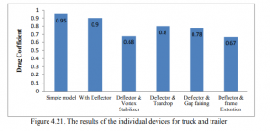
Figure 1: Individual drag coefficients of the modifications
(Source: http://i-rep.emu.edu.tr:8080/jspui/bitstream/11129/4160/1/shirihamidreza.pdf)
The results showed that two critical areas for the development of vortex and drag force
- The flow structures in the gap between trailer and cab
- The flow structures near the rear of the trailer
This research work studied the effect on the aerodynamic efficiency of a truck with the help of five modification devices. In further research studies, more methods should be considered to pick the best equipment.
The effect of aerodynamic forces on the resistive force encountered by a vehicle is immense. This affects the vehicle’s fuel consumption to a great extent. Around 60% of the total resistive forces encountered by the vehicle comes from “aerodynamic drag”. In the works of (Shakti, 2018), the researchers set out to find a solution to the problem of drag force encountered on a trailer.
The objective of the paper was to find out techniques to minimize the drag force encountered by the truck when it is in motion. The researchers believed that the fuel economy of trailers is vital because trucks are poorly designed when it comes to aerodynamic considerations.
This comes from the traditional view that aerodynamic analysis is essential for “performance vehicles” only. However, as more vehicle manufacturers are becoming aware of the importance of fuel economy along with the customers, it becomes essential for truck makers to think about the aerodynamics of their vehicle. In the research, currently being studied, the researchers found three key areas where the majority of the drag forces in the trailer appeared.
These three areas were the frontal+rear areas which accounted for 25% of the total drag, the under-carriage+tyres which accounted for 35% of the full pull and the gap between cabin-container that accounted for 15% of the entire drag force. Considering that a large trailer was going at a velocity of close to 80kmph, it would consume close to 47% of its fuel to overcome just the “aerodynamic drag”.
CFD analysis can help improve the design of the truck and make it more aerodynamic. This will improve the “fuel efficiency” of the trailer by reducing the drag force it encounters during its traverse. Aerodynamic design modifications do not affect the overall engine output.
Therefore a small design improvement makes the vehicle mostly efficient without even touching its engine. The new trailer designs such as “teardrop trailer” and the “drag-reduction devices” can give an improvement in the “aerodynamic resistance” which can provide approximate fuel savings of 8%.
This research also further invested the effects of “aerodynamic noise” on the performance of the vehicle. The causes of “aerodynamic noise” are from holes/gaps in doors, windshield, hood and frontal area as the air passes through these orifices.
Noise can be heard in trailers when there is a window which is partly opened, and this noise is of a “low frequency” (approx. 10Hz). The real reason behind this phenomena is the “Helmholtz resonance of the trailer cabin”, and it is triggered as the air flows past the cabin.
In order to understand the problem of aerodynamic resistance, a proper model has to be developed that will consider not only the effects of drag but also aeroacoustic considerations will have to be made.
Along with these models, the trailer also experiences a significant resistance as it moves over wet tracks, these considerations are also important when it comes to the question of improving “fuel efficiency” of commercial vehicles.
In this report, the results of a CFD simulation with a box-trailer will be studied, and conclusions will be done based on those results. The modelling of the box trailer was done with the appropriate CAD tools. The geometric modelling of the box-type trailer is shown in the figure below:
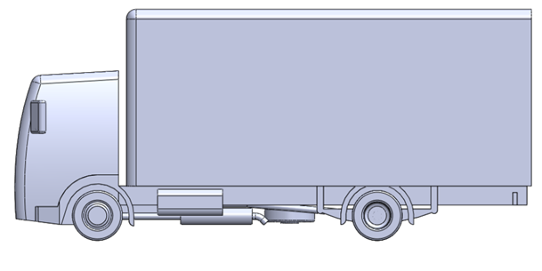
Figure 2: The geometric design of the box-trailer
(Source: given)
The CFD analysis was conducted in ANSYS CFX, and this is a program that has the adequate functionality and the attributes required for the modelling of flows around complex solid boundaries (Liuet al. 2019).
The Testing of the model in the software will require several inputs from the user that will determine the properties of the fluid under the conditions in which this model will be tested. Another data that has to be provided to the software after importing the presented model is the speed of air.
The rate of air which is to be considered for this experiment is 50mph. Together with the two parameters, temperature and wind speed set all the necessary conditions related to the physical properties of the wind. The “blockage ratio” of the wind tunnel is the ratio of the “frontal area” of the vehicle and the CS area of the “wind tunnel”.
In order to get the best results from the simulation, the “blockage ratio” must be made as small as possible (Asimet al.2020). However, a lower blockage ratio also means a more extensive domain for airflow, and this significantly affects the time to compute results. For this experiment, a “blockage ratio” of 9% was used in the computation. It has been observed that increasing the “blockage ratio” can increase the drag forces encountered by the vehicle.
Therefore, it is necessary that experiments are conducted on the effect of “blockage ratio” on the “aerodynamic drag” of the vehicle. The other factors that are necessary to be studied are the “distribution of pressure”.
The simulation studies have shown that the maximum pressure occurs in the front of the vehicle where the air hits the front end of the truck. This is expected because the velocity of the airflow is zero when considered relative to the truck. As a result, the kinetic energy of the fluid is transformed into the pressure energy, thus, giving an immense pressure value towards the front end of the truck.
The first thing that comes to mind when discussing aerodynamic drag is smoothing edges and corners. The “drag force” is induced for two reasons; one reason is the skin friction which is the frictional force acting between the robust edges and the flowing fluid. In addition to this, any abrupt changes in the direction of the fluid cause thrust forces or regions of high pressure (Shakti, 2016).
This component of drag is more top in case of truck and trailers. So it is essential to introduce smoothness into the edges of the container so that the effect of sharp corners is minimized (Ijnrd.org, 2020).
Even though it is possible to reduce the drag to some extent by removing sharp edges from the design of the truck, the large frontal area means that there will still be a considerable amount of force acting on the truck due to thrust forces towards the front of the truck.
However, the filleting of the upper and lower sides of the cabin has a small effect on pressure distribution towards the front of the truck.
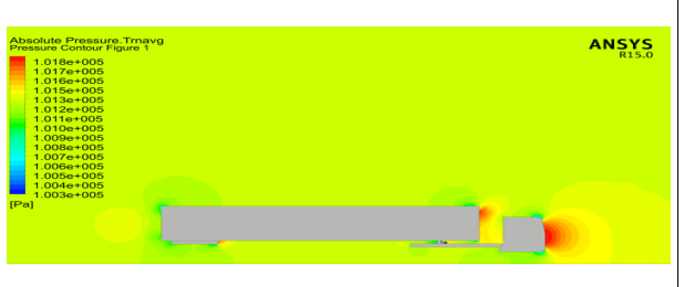
Figure 3: Pressure distribution around the truck in 2 dimensions
(Source: ANSYS CFX)
Another critical analysis is that of the “velocity contour model”. These diagrams represent the velocity of the flow around the solid surfaces as the air moves past it. This is important because the reduction in air velocity indicates that the truck is opposing the flow of fluid around its edges.
The main concern for the engineer here is to design the truck so that it offers minimum resistance to the flow of air past it. Since the entry velocity of the air is 50mph, the model provides some resistance to the airflow (Vohraet al.2018).
Thus the air velocity reduces to some extent, and this is evident in the picture of the “velocity contours” which indicates the speed of air in the x-direction all around the solid geometric structure of the vehicle.
It has been observed that the effect of smoothing the edges of the model has a significant impact on the velocity distribution in the “cabin-trailer gap” (Iop.org, 2020).
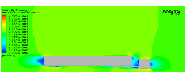
Figure 4: Velocity contours showing the velocity of air as it flows past the model in 2D
(Source: ANSYS CFX)
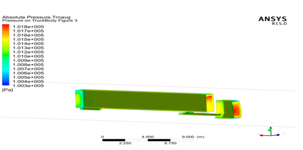
Figure 5: The pressure distribution across the surfaces of the trailer in 3D
(Source: ANSYS CFX)
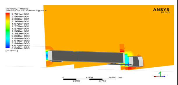
Figure 6: The velocity contours for the model in 3D
(Source: ANSYS CFX)
It has been mentioned earlier also that the designs of trailer software are particularly aerodynamic. To make the trailers more aerodynamic and increase their fuel efficiency, they have to be fitted with some modifications that reduce the effect of drag on the geometry of the body.
One such change has been tested here, and it is the deflector (Humphreys, 2017). The deflector is used on top of the cabin, and it has the effect of reducing the “aerodynamic drag” on the vehicle because of the increased efficiency with which it handles the flow in the “cabin-trailer gap” (Ijrter.com, 2017).
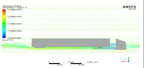
Figure 7: Effect of deflector on the aerodynamic performance of the truck
(Source: ANSYS CFX)
Another modification to the geometry of the trailer that improves its aerodynamic efficiency is the teardrop. A teardrop is a particular type of container that has been manufactured keeping in mind “aerodynamic considerations”. The results show that the teardrop improves the efficiency of the model by
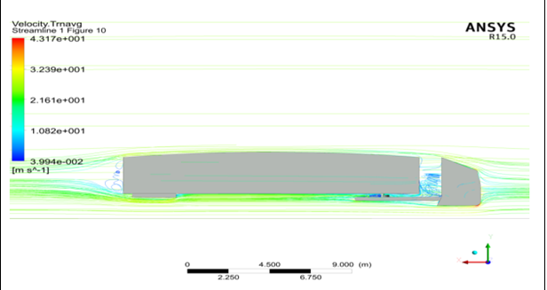
Figure 8: Effect of a teardrop on the aerodynamic performance of the model
(Source: ANSYS CFX)
Figure 8 shows the effect of the two modifications that were made to the design to improve “aerodynamic performance”.
In the previous section, it has been discussed how the pressure at the front of the vehicle is high because of the air directly hitting a flat surface and losing all its velocity. In order to reduce the impact of the blow, the design of the vehicle must be changed so that the air can split the moment it strikes the solid surface and therefore retaining a significant portion of its velocity.
This improves aerodynamic performance and reduces the resistive force on the vehicle. In effect, it has a very high potential for reducing the fuel consumption of trucks or trailers. There are several other effects that have to be observed in order to understand the overall impact of the “aerodynamics of the vehicle”.
As the flow of air separates from the top and bottom of the cabin, there’s a chance that vortexes will be formed due to the phenomena called flow separation. These vortexes are a cause of turbulence, and in order to reduce the effect of turbulence, the edges of the truck are rounded.
This creates a more subtle change in direction so that the flow does not have too much trouble to come into contact with the solid surface again (Alonso-Estébanezet al.2017). The same problem happens at the gap between the trailer and the cabin and also towards the rear of the container.
Therefore, in these locations there is a likelihood for the formation of turbulence. The structure of turbulence impacts drag greatly. Turbulence is seen as dis-oriented energy and results in energy losses from the vehicle if it comes into contact with the vehicle.
In order to avoid the chances of turbulence, the truck geometry needs to be modified so that the areas where turbulence have a possibility to occur is altered or covered. The modification to the truck structure has been discussed in the section “Literature Review”.
The effect of modifications is that the geometry is altered to that flow path changes with the result of a reduction in drag force. The first modification that was made is the deflector. The deflector helps to reduce the chance of flow separation at the upper edges of the cabin and is especially helpful for aerodynamic performance at high speeds.
The other modification which has been suggested in this report is the teardrop (Xuand Zhou, 2018). The teardrop is a more bulging trailer shape that helps to keep the flow in contact with the surface of the trailer as the flow moves past the truck.
With a teardrop, the airflow keeps in contact to the surface of the trailer, and therefore there is a lesser chance of separation to occur at the upper edge of the trailer and also at the rear end. This improves aerodynamic performance considerably (I-rep.emu.edu, 2016).
In the experiment conducted on the model of the box-type trailer, there are still two areas that are not sufficiently addressed in this exercise. These two areas are
- The increase of air pressure in the front of the cabin. This increase of air pressure is observed as a result of the large frontal area of the cabin, and this leads to a large amount of thrust force at the front end of the truck.
- The tyres of the truck are another area that requires attention. The profile and geometry of the tyres and the fact that they remain unprotected means that they abruptly cause changes in the flow direction (Praveenet al.2017). Therefore, the tyres are the main concern for the consideration of aerodynamic forces in the truck. The impact of their geometry on the aerodynamic performance of the truck should be studied, and measures of improving its performance must be thought about.
The aerodynamic performance of the box-trailer requires improvements because its aerodynamic performance is likely to harm its fuel efficiency. Vehicles today must be manufactured so that the risk it poses to the environment can be minimized.
The environmental risk posed by commercial vehicles is very high due to the inefficient design that makes it use large quantities of fuel in order to produce a minimal effect on output. So designing a more slippery vehicle is important so that its performance and fuel efficiency are improved.
This is one of the most important sustainability concerns that is spreading all over the automobile industry at present. The performance of trucks can be improved by adding some modifications to the design of the truck.
These modifications can come in the form of deflectors or teardrop-shaped trailers. Together these two modifications can improve the performance of the box trailer by close to 10%, which is quite significant.
Journals
Alonso-Estébanez, A., Díaz, J.D.C., Rabanal, F.Á. and Pascual-Muñoz, P., 2017. Performance analysis of wind fence models when used for truck protection under crosswind through numerical modelling. Journal of Wind Engineering and Industrial Aerodynamics, 168, pp.20-31.
Asim, T., Ubbi, K., Mishra, R. and Nsom, B., 2020. Effect of surface roughness on the aerodynamic performance of an articulated truck-trailer assembly.
Humphreys, H., 2017. A Computational Fluid Dynamics Analysis of a Driver-Assistive Truck Platooning System with Lateral Offset.
Liu, J., Zhuang, C., Liu, S. and Zhou, H.M., 2019, October. Numerical simulation of heavy truck’s aerodynamic noise. In IOP Conference Series: Materials Science and Engineering (Vol. 657, No. 1, p. 012070). IOP Publishing.
Praveen, L., Venugopal, L., Monica, T., Kumar, C.L. and Reddy, K.R.S., 2017. DESIGN AND ANALYSIS MODIFIED TRUCK. International Journal of Civil Engineering, 8(7).
Shakti, P., 2016. Aerodynamic improvement for tipper.
Vohra, V., Wahba, M., Akarslan, G., Ni, R. and Brennan, S., 2018, August. An examination of vehicle spacing to reduce aerodynamic drag in truck platoons. In 2018 IEEE Vehicle Power and Propulsion Conference (VPPC) (pp. 1-6). IEEE.
Xu, J. and Zhou, S., 2018. Flow field analysis of trucks and design of an additional drag reduction device. Engineering Review: Međunarodni časopis namijenjen publiciranju originalnih istraživanja s aspekta analize konstrukcija, materijala i novih tehnologija u području strojarstva, brodogradnje, temeljnih tehničkih znanosti, elektrotehnike, računarstva i građevinarstva, 38(1), pp.70-78.
Online articles
Ijrter.com, 2017, Aerodynamic Analysis of vehicles using CFD, available at https://www.ijrter.com/papers/volume-3/issue-3/aerodynamic-analysis-of-vehicle-using-cfd.pdf, [accessed on 05.04.2020].
I-rep.emu.edu, 2016, Aerodynamic Analysis of Drag Reduction Devices on the Simplified Body for Tractor and Trailer by Using CFD, available at http://i-rep.emu.edu.tr:8080/jspui/bitstream/11129/4160/1/shirihamidreza.pdf, [accessed on 05.04.2020].
Websites
Ijnrd.org, 2020, EFFECT OF EXTERNAL AERODYNAMIC, AEROACOUSTICS AND AQUAPLANING & HYDROPLANING ON COMMERCIAL VEHICLE PERFORMANCE: CFD INVESTIGATION ON TRAILER TRUCK, available at: http://www.ijnrd.org/papers/IJNRD1802006.pdf, [accessed on: 05.04.2020].
Iop.org, 2020, Numerical analysis on the aerodynamic performance of different automobile body shape, available at https://iopscience.iop.org/article/10.1088/1755-1315/242/3/032027/pdf, [accessed on 05.04.2020].
