
Electric vehicle motor controller using Arduino
ABSTRACT
Transportation system plays an immense role in human often life. The larger part of this transportation system is built on fossil fuel transport system. This transport system deploys internal combustion system (ICE), which causes emission and environmental menace.
Some unfavorable circumcenters in the ICE persuadeto make utilize of an ElectricVehicle and Hybrid Electric Vehicle. Essentially the electric vehicles are three types, pure electric vehicles (EV), hybrid electric vehicles(HEV), plug-in hybrid electric vehicles(PHEV).
Hybrid vehicles (HVs) possess the superiority of both internal combustion. Arduino based control system has been used to management strategies for power design in parallel HVs and it improves the performance of hybrid vehicles.

Keywords – electric vehicles, hybrid electric vehicles, plug in hybrid electric vehicles, Arduino control system, power electronic devices.
1. INTRODUCTION
In the modern technology the evolution of internal combustion of engine vehicles (ICEVs), especially automobilesare the greatest achievement. But, vast number of automobiles throughout the world causes dangerous threat to environment and human life. In recent times, the research and development activities allied to transportation system accentuate the development of high efficiency, clean and safer operations.
Electric vehicles (EV), Hybrid electric vehicles (HEV’s), plug in hybrid electric vehicles (PHEV’s), fuel cell vehicles (FCV), haven consistently recouped the ICE vehicles. As we know that, the hybrid electric vehicles conventional internal combustion engine and an electric propulsion system.
Fuel cell (FC) technologies familiar to become to an attractive power sources for automotive applications for their safer, high efficiency, high reliability. The polymer electrolyte membrane antiquated to be the prime candidate.
By the reason of PEMFC has high power density with lower operating temperature when it compared to other types of FC systems. So, the FC can be varied with energy storage systems to raise the performance of it during the transient and peak power demands of HEV’s and to restore the energy through regenerative braking.
The main difference between PHEV’s and HEV’ s is, the PHEV’s has the on-board battery pack, which can be charged through an external electricity sources. EV’sand PHEV’s salvage the energy through the present of regenerative braking during the deceleration cycle.
The battery and ultra-capacitors are used to store this generated energy’s. PHEV’s possess flatter some fascinating conventional vehicles through their zero emission, low consumption of fuel and size of batteries on board and also PHEV’s provides remarkable enhanced performance and flexibility when estimated with conventional vehicles.
Battery powered electric vehicles are clean and safer to use, it also better for the good environment and global warming. However, the circumstance of battery powered electric vehicles are expensive in cost, short driving distance, is take more time to charge the battery. This paper going to present the technology of current Electric vehicles(EV’s).
2. GENERAL CLASSIFICATION OF ELECTRIC VEHICLES
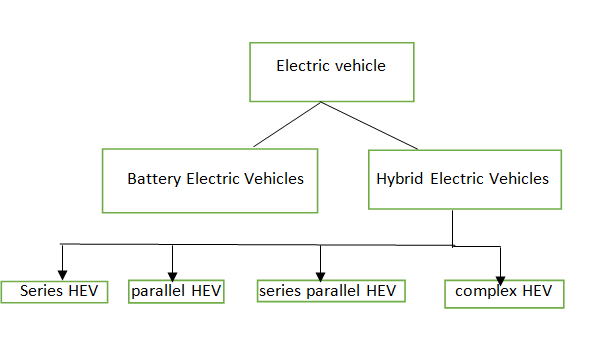
Electric vehicle
Battery Electric Vehicles Hybrid Electric Vehicles
Series HEV parallel HEV series parallel HEV complex HEV
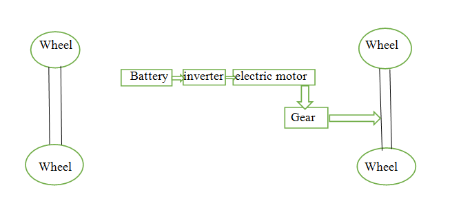
Figure 1. classification of EV’s
Fig 1 showing the clear explanation of electric vehicles. There are mainly two types, Battery Electric Vehicles(BEV’s), Hybrid Electric vehicles(HEV’s). Battery Electric Vehicles makes the usage of batteries for the storage of the energy that will be converted in to mechanical power by an electric motor; Here ICE is absent in this case. Hybrid Electric Vehicles are combination of ICE and Electric Motors. Further paragraphs are going to explain about the function and working of EV, HEV’s.
1. Electric Vehicles
Wheel Wheel
Battery inverter electric motor
Gear
Wheel Wheel
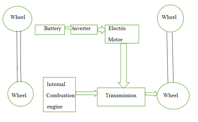
Figure 2. Electric vehicle
Fig2 shows the simple Electric Vehicle. Frenchman Gustave Trove was the first man who inventedthe Electric Vehicles in 1881s. it was a tricycle operated by 0.1 HP DC motors supply with lead acid batteries. Electric vehicle uses an electric motor for the better friction and energy sources feasibly fuel cells, ultra-capacitors, chemical batteries. The electric vehicles consists with more advantages than the conventional internal combustion engine vehicle like as lower emission, great efficiency, clean and smooth operation.
2. Hybrid Electric Vehicles
Wheel Wheel
Battery inverter Electric
Motor
Internal
Wheel Combustion Transmission Wheel
engine
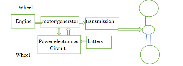
Figure 3. Hybrid Electric Vehicles
The first series Hybrid Electric vehicles are extracted from the pure Electric vehicle commercially raised by the French firm Vaudeville and priestly. A hybrid electric vehicle which is combines an internal combustion engine propulsion and electric propulsion engine system. HEV rescue the energy and minimize the pollution by combing the Electric motor and ICE. An HEV is the self-chargedmaterial it never has to be plugged in.
3. The series Hybrid Electric Vehicle
Wheel
Engine motor/generator transmission
Power electronics battery
Circuit
Wheel
In fig4 exabitsthe series HEVs. The generator controlled by the engine In the HEVs, which in turn, electric motor. The wheels are operated only by the electric motor which also control as a generator.
The internal combustion engine which control the electric generator and it supplies to electric power to the motor and batteries. In common an engine coupled to a generator produces to power to charge the battery. An electric motor connected to drive train, ICE can run extreme fast to operate the generator and it help to reducing the emission.
The main advantages of series HEVs is ICE run at optical speed, torque and it consumes less fuel produces high efficiency. The main disadvantage is it uses only one ICE, one electric motor, one generator.
4. Plug in hybrid electric vehicle
Wind energy combustion engine
Solar energy power grid regenerative braking
Thermal energy electric motor generator
Battery
Generally, the plug in HEVs uses two propulsion technologies to operate the vehicle. One is electric propulsion technology and another one is gasoline propulsion engine, mainly used to raise the fuel economy and the batteries is plugged into external electric power grid. PHEVs battery have a battery pack of high energy density and run solely when it compared to other HEVs it also helps to minimize the usage of ICE, itincreasesthe fuel efficiency and reduce the emission.
Electric vehicle motor controller concept
Electric motors are playing a key role in the triumph of EVs, HEVs and FCV. There are three important modes of electric motors for EVS, HEVs and FCV. There is motor controller, battery system, AC motor. The essential motor and drive technology contain high torque density, power density, high speed range include constant torque and constant power operation, high efficiency over a high range speed, high reliability and reasonable cost.
U
V
W
DC link
Dc link capacitor
Generally, the management system of battery is any electronic technique runs a restorable battery (cell or battery pack), like as by saving the battery from controlling from outside its safe operating area, BMS monitors it states, calculating the secondary data, controls its environment.
Battery pack always builds together with a battery the board framework with an outer correspondence information transport is a keen battery pack. A smart battery charged used to charge the smart battery pack. The battery system is connected to motor controller using DC link.
Motor controller
Actually, the potential of the vehicles electric motor, while in other vehicles is calculated in kilowatts (KW). 100 kw is roughly equivalent to 134 horse power, then in electric motors can operate their extreme torque over a wide RPS range. This means that the operation of a vehicle with a 100 kw electric motor beats that of a vehicle with a 100-kw internal combustion engine, which can only deliver its maximum torque within a controlled range of engine speed.
Energy is vanished throughout the process of transforming the electrical energy to mechanical energy. Almost 90% of the energy from the battery is transformed to mechanical energy, the losses being in the motor and drivetrain.
Mostly, direct current (DC) electricity is sustained into a DC/AC inverted where it is switched to alternating current (AC) electricity and this AC electricity is associated to a 3-phase AC motor.
For electric cars, forklift trucks, and trains, DC motors frequently used. In some circumstances, unanimous motors are used, and the AC or DC may be engaged. In current invention vehicles, numerous motor types have been executed, for example: induction motors within Tesla motor vehicles and permanent magnet machines in the Nissan Leaf and Chevrolet Bolt.
Batteries
Batteries remains energy sources for the EV and HEVs. A BMS may also future a recharge system admitting a secure way to associate the battery to different loads and reducing the extreme inrush currents to load capacitors.
The connection to load is usually controlled through electromagnetic relays called contactors. The precharge circuit can be either power resistors connected in series with the loads till the capacitors sore charged.
Otherwise, a switched mode power supply coupled in parallel to load can be use up to charge the voltage of the load circuit equal to battery voltage with the intention to allow closing the contactors between battery and load circuit. A BMS might have a circuit that can test whether a relay is already before precharging to prevent inrush current to occur.
Charging speeds and connectors
Rapid chargers
- 50KW DC charging on one of two connector type
- 43kw dc charging on one connector type
- 120kw dc charging on tesla supercharger network
- All rapid units have tethered cables
EV battery charger components
DC power to batteries
AC power in
communication to user
communication to
car -end use
Tools used for modeling and simulation
Arduino
Arduino programming is an incorporated advancement condition (IDE) is a cross stage application written in java, and works from the IDE for the preparing programming language.
Arduino based controller utilizes Arduino board (Arduino mega 2560 R3). Which is microcontroller board it has 54 I/o, o/p sticks in that 15 pins can be utilized as a heartbeat width balance (PWM) yield. 16 of simple information sources, 4 UARTs (equipment sequential ports). A 16 MHz precious stone oscillators. with a USB association, a power jack, alongside a reset catch. It contains everything expected to help the microcontroller. We have to give the association with PC with a USB link or interface with AC TO DC connector to begin. The Arduino Mega can be modified with Arduino programming.
Arduino code:
Transformer calculation
Capacitance value:
C1 = Iripple/ (fsw * Vripple * 8)
Iripple = 10 % of load current
Load current = 10 Ampere
Vripple= 25mV
C1 = 1 / (8* 25 * 10-3 * 18000)
= 270 μF
Conductance value:
L1= △ V * dt / di = (Vs – Vo) dt/ Iripple
Vs = Vo * 2 = 25 * 2 = 50
dt = (δ/ 2) * (1/fsw) = (0.8/2) * (1/18000)
dt = 20 * 10-6
Therefore, L1 = ((50-25) * 20 * 10-6) / 1 = 500 μH
Primary and secondary winding:
Vin= 34 V
Vout= 25 V
Np = (Vp * ton)/(dB * Ac)
ton= (1/ switching frequency) * δmax / 2
δmax = 0.8
fsw = 18000 Hz
dB of ETD material is 490
Ac = Cross sectional area of core = 76 mm2
Np = (34 *(0.8/2) * (1/18000)) / (2* 10 –3* 490 * 76 * 10-6) = 10
As we know, NP / Ns = Vp / Vs
Therefore, Ns = (10 * 25) / 34 = 7.35
So, the value of the primary winding is 10 and the value of secondary winding is 7.
