
Great KB7045 W P A H R E Systems Assignment Sample
Introduction
Present report focuses on the analysis of HRES (Hybrid Renewable Energy System) and its creation using wind power. These systems are the future of this world.
Growing concern about fossil fuel extinction and overuse of non-renewable energy sources has resulted most of the countries to focus on methods to develop hybrid systems. Hybrid systems use renewable as well as non-renewable sources of energy to store and deliver energy.http://Great KB7045 W P A H R E Systems Assignment Sample
This report will focus on the basics of an HRES along with the fundamental principles of the system. The conceptual design will be presented along with its stochastic modelling for cost.
Theoretical Background

HRES are getting popular day by day and people are even more interested in installing such systems at their homes and workplaces. HRES is a hybrid power system which critically uses power for a renewable source and couples it with the store’s non-renewable power.http://Great KB7045 W P A H R E Systems Assignment Sample
This makes the system even more powerful and capable of delivering and storing charges. According to the views of Khari et al. (2016), wind speeds and sunshine matters the most in case of HRES designs. Most of the HRES used throughout the world uses solar and wind power. Their HRES are placed and designed according to a geographical location.
Places which are less susceptible to sunlight get an extensive amount of wind and vice versa, these systems critically take advantage of nature and output huge amounts of storable energy.http://Great KB7045 W P A H R E Systems Assignment Sample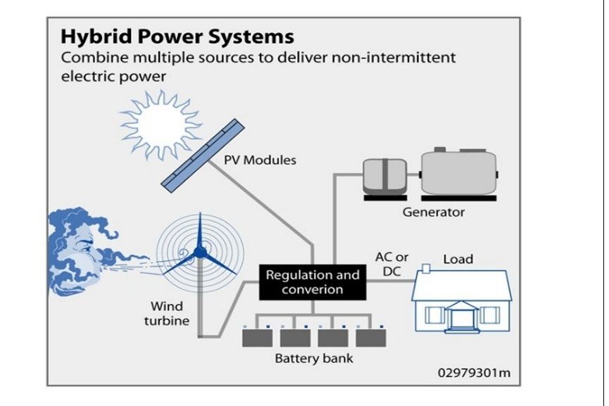
Figure 1: HRES
(Source: Al-Falah et al. 2017)
One of the most significant aspects of an HRES is that it can produce power throughout the year. Solar energy and wind energy are stronger at different times in a year and HRES can take advantage of a seasonal change.http://Great KB7045 W P A H R E Systems Assignment Sample
Based on a study by Al-Falah et al. (2017), most of the HRES operating all around the world is stand-alone systems. These systems entirely operate off-grid which is not connected to electricity distribution and generation system.
There are several times in a year where there is an absence of wind and solar energy. In these times, an HRIS drives through batteries. These are stored power from the previous collection. It can happen that a battery of an HRES fails to deliver; in such case the diesel-powered engine will recharge the batteries.
Addition of an engine to an HRES is another complex engineering as these systems mostly work automatically. As per the study by Kaljo et al. (2016), switching the diesel-generated engine on and off can only be done manually.http://Great KB7045 W P A H R E Systems Assignment Sample
Implementation of automation on such engines is difficult and will cost extensively more. Size of the overall HRES is an issue as diesel-powered engines take up a huge amount of space.
Fundamentals of HRES
HRES are made up of different components. There are many areas in the world where an HRES can be extremely cost-effective. HRES are more popular in remote locations where there is a scarcity of power.http://Great KB7045 W P A H R E Systems Assignment Sample
Stand-alone systems are always less costly since they are extended towards an electricity grid. As stated by Jung and Villagran (2017), the cost of such complete systems is around £10000 to £35000.
There are several strategies of using an HRES, most popular among all systems are the use of fossil fuel for initial and extra power. There are several components of an HRES such as batteries, charge controller, power conditioning equipment, meters, instrumentation and safety equipment.http://Great KB7045 W P A H R E Systems Assignment Sample
System Level
Hybrid systems can be of two types concerning power generation from wind and solar energy. System-level integration for an HRES is almost similar for a wind or solar power generation system. The main energy generation panel can be replaced with secondary sources.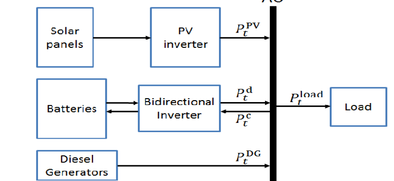
Figure 2: System-level integration of an HRES
(Source: Announce et al. 2018)
As seen from the above image, the solar panels and batteries are all connected to inverters. These inverters are responsible for interpreting the power. Power inputs from the solar panel are DC inputs.http://Great KB7045 W P A H R E Systems Assignment Sample
These DC inputs cannot be read by the AC power load. According to Goel and Sharma (2017), these DC inputs are all converted with the help of PV inverter in an AC output. The power is then passed through an AC layout and is stored inside the batteries.http://Great KB7045 W P A H R E Systems Assignment Sample
Batteries on the outer line are all connected to the bidirectional inverter.
A bidirectional inverter can convert both AC and DC units of energy. Batteries are mostly new generation technologies and are responsible for AC power generation.
There is an extensive amount of power stored inside the entire energy line of this system. The diesel generators in the system are always connected to the main source. Whenever the system goes offline or runs out of power, these generators are responsible for turning the entire system on with the help of non-renewable sources of energy.http://Great KB7045 W P A H R E Systems Assignment Sample
According to Malaki et al. (2017), all the generated power is then passed through the AC line and the power stored inside the load in AC units.
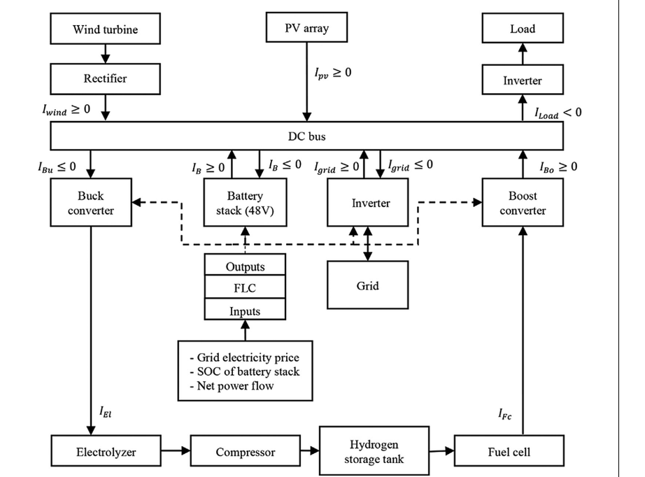
Figure 3: Components of an HRES
(Source: Malaki et al. 2016)
There are several components of an HRES. The above image represents a complex HRES with several components that are responsible for power generation with the use of gas energy.http://Great KB7045 W P A H R E Systems Assignment Sample
As per the study by Rahman et al. (2016), a complex HRES will include more than ten to fifteen components. It can be seen that the energy collected through the wind turbine is passed through a reflector for conversion.
That reflector is connected to a DC bus where all the power is stored and then transferred into AC power.
Buck and Boost converters are used in order to convert the energy released from the fuel cells. Battery and the inverter are connected with the bus to supply power. Both the converters are internally connected and are passed through the grid for power unit confirmation (Malaki et al. 2016).http://Great KB7045 W P A H R E Systems Assignment Sample
All the materials connected to the bus are finally connected to the load where the entire power of the system is stored.
Conceptual design of the HRES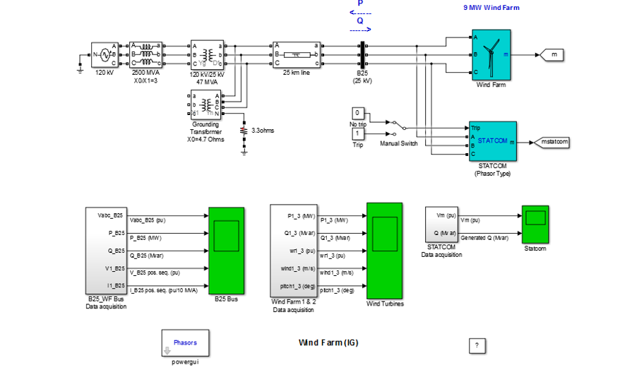
Figure 4: Wind-PV-Battery-Diesel generator HRES
(Source: MATLAB)
The above image critically describes a wind farm which consists of six 1.5 MW turbines that are directly connected to a 25 kV power distribution system.http://Great KB7045 W P A H R E Systems Assignment Sample
This system generates and exports power to a 120 kV grid through a 25 km long, 25 kV feeder. 9 MW wind farm is entirely simulated by 3 similar pairs of 1.5 MW turbines. Stator winding present in the system is directly connected to the 60 Hz power grid.
The rotator of the system is entirely controlled by the Variable pitch turbine. Pitch angle of this system is extensively controlled in order to control the generator output for specific values. These values are greater than 9 m/s. Speed of the turbines mostly varies in between the range of 1 put at 0 load and 1.005 put at complete load.http://Great KB7045 W P A H R E Systems Assignment Sample
Induction generators’ reactive absorption power is entirely compensated by few capacitor banks. These are placed across wind turbines. These are low voltage buses, each consisting of 400 knar in 1.5 MW turbines. The left reactive power is needed in order to maintain 25 kV voltages at B25. The droop setting of the entire system is set to 3%.
Once the simulation of the entire system has started, each pair of turbines connected inside the system starts smoothly. The maximum value reached by each of the turbines is approximately 3MW.http://Great KB7045 W P A H R E Systems Assignment Sample
This speed is reached within a span of 8 seconds. When the output speed reaches this limit, the degree of the turbines is now changed from 0 degrees to 8 degrees. Within the operational time frame, the maximum speed of the turbines will be in between 1.0028 up to 1.0047 put.
At an initial stage, the pitch angle of the turbine is at zero. The absorbed reactive power of the turbine increases gradually towards the nominal power. Each of the powers present in the system absorbs 14.7 Mar.http://Great KB7045 W P A H R E Systems Assignment Sample
The system is designed to restrict the speed at 9 m/s, however, when the speed reaches at 11 m/s, total power exported which is measured in the bus is around 9 Mv. Starcom present in the system maintains a voltage of 0.984 put while generating 1.62 Mar.http://Great KB7045 W P A H R E Systems Assignment Sample
Advanced Stochastic Modelling
Hybrid systems are dynamic systems which are used in order to assess interaction among different dynamics. Based on a study by Halaby and Makhila (2018), discrete and continuous dynamic states are considered in case of hybrid systems.
A system can be said as discrete when it takes only finite values in inputs. A system can be said as continuous when it takes values in a perfect Euclidean space, that is Rn where the number of n is greater than zero.http://Great KB7045 W P A H R E Systems Assignment Sample
The hybrid automation H is, H = (Q, X, I n i t, f, I, E, G, R)
Where, [Q can be said as a set of discrete variables, Q is also countable]
[X is the set which defines continuous variables]
[I n i t < Q * X], this is a set representing initial state of a system.
[FAQs * X -> T X], this is a vector field.
[I n v: Q -> P (X)2X], assigns to each value of q Σ Q an invariant set;
[E < Q * Q], this is a collection of discrete transition;
[G:E -> P ((X)], this value particularly assigns to each e, where e = (q, q) Σ E;
[R:E * X -> P((X)], this value assigns to each of e, where e = (q, q) Σ E; along with x < X. This is a reset relation.
In case of randomness of the system, flow of f will be calculated as Φ:𝒟 × ℝ → 𝒟
The value of Φ is, Φ (α,t) ∈ Q;
Along with Φ (α,t) ∈ X(i);
Each of the values can be calculated with the help of PDMP (Piecewise Deterministic Markov Process) where the set of this equation stands as H = ((Q, d, X), f, I n i t, λ, R)
Q is a set of discrete countable variables;
d:Q → ℕ, this is defining the state of equal spaces;
X:Q → ℝd(.), this is responsible for mapping i ∈ Q into a subset X(i) of ℝd(i)
The final equation will be R:ℬ (𝒟∞) × 𝒟∗ → [0,1]
MATLAB Code
### Invoking Target Language Compiler on power_wind_ig.rtw
### Using System Target File: C:\Program Files\MATLAB\MATLAB Production Server\R2015a\rtw\c\grt\grt.tlc ### Loading TLC function libraries
### Initial pass through model to cache user defined code
### Caching model source code
### Writing header file power_wind_ig.h
### Writing header file power_wind_ig_types.h .
### Writing header file power_wind_ig_private.h
### Writing header file rtwtypes.h
### Writing header file builtin_typeid_types.h
### Writing header file multiword_types.h
### Writing header file zero_crossing_types.h .
### Writing header file rtGetInf.h
### Writing source file rtGetInf.c
### Writing header file rtGetNaN.h
### Writing source file rtGetNaN.c
### Writing header file rt_defines.h
### Writing header file rt_look1d.h .
### Writing source file rt_look1d.c
### Writing header file rt_look.h
### Writing source file rt_look.c
### Writing header file rt_nonfinite.h
### Writing source file rt_nonfinite.c
### Writing source file power_wind_ig.c
### Writing header file rtmodel.h .
### Writing source file power_wind_ig_data.c
### TLC code generation complete.
### Creating project marker file: rtw_proj.tmw
### Using toolchain: Microsoft Visual C++ 2010 v10.0 | nmake (64-bit Windows)
### Creating ‘D:\Work\April\6\2000 (RAK-APR-050420-0856PM-#1707175-0704-A-Assignment)\power_wind_ig_grt_rtw\power_wind_ig.mk’ … ### Building ‘power_wind_ig’: nmake -f power_wind_ig.mk all
Building Code. [Refer to Appendix 1]
Conclusion
Based on the above analysis on HRES it can be concluded that HIRES are growing in popularity among people. Use of renewable energy is a necessity nowadays as the world is running out of fossil fuel.
The creation of HRES is complex and requires extensive engineering techniques. It has been found out that these systems require appropriate input to produce the resultant output. Use of solar and wind energy are the most common examples of a HRES.http://Great KB7045 W P A H R E Systems Assignment Sample
Creation and functions of an HRES is entirely based on geographical locations. Power generated from sources of wind energy is easier to process. It has been found out that interpreters and converters are one of the main components of an HRES. The report includes a design of HRES created via MATLAB software.http://Great KB7045 W P A H R E Systems Assignment Sample
References
Al-Falahi, M.D., Jayasinghe, S.D.G. and Enshaei, H.J.E.C., 2017. A review on recent size optimization methodologies for standalone solar and wind hybrid renewable energy system. Energy conversion and management, 143, pp.252-274.
Anoune, K., Bouya, M., Astito, A. and Abdellah, A.B., 2018. Sizing methods and optimization techniques for PV-wind based hybrid renewable energy system: A review. Renewable and Sustainable Energy Reviews, 93, pp.652-673.
Goel, S. and Sharma, R., 2017. Performance evaluation of stand alone, grid connected and hybrid renewable energy systems for rural application: A comparative review. Renewable and Sustainable Energy Reviews, 78, pp.1378-1389.
Halabi, L.M. and Mekhilef, S., 2018. Flexible hybrid renewable energy system design for a typical remote village located in tropical climate. Journal of cleaner production, 177, pp.908-924.
Jung, J. and Villaran, M., 2017. Optimal planning and design of hybrid renewable energy systems for microgrids. Renewable and Sustainable Energy Reviews, 75, pp.180-191.
Kamjoo, A., Maheri, A., Dizqah, A.M. and Putrus, G.A., 2016. Multi-objective design under uncertainties of hybrid renewable energy system using NSGA-II and chance constrained programming. International Journal of Electrical Power & Energy Systems, 74, pp.187-194.
Khare, V., Nema, S. and Baredar, P., 2016. Solar–wind hybrid renewable energy system: A review. Renewable and Sustainable Energy Reviews, 58, pp.23-33.
Maleki, A., Khajeh, M.G. and Ameri, M., 2016. Optimal sizing of a grid independent hybrid renewable energy system incorporating resource uncertainty, and load uncertainty. International Journal of Electrical Power & Energy Systems, 83, pp.514-524.
Maleki, A., Rosen, M.A. and Pourfayaz, F., 2017. Optimal operation of a grid-connected hybrid renewable energy system for residential applications. Sustainability, 9(8), p.1314.
Rahman, M.M., Khan, M.M.U.H., Ullah, M.A., Zhang, X. and Kumar, A., 2016. A hybrid renewable energy system for a North American off-grid community. Energy, 97, pp.151-160.
Appendix
Appendix 1
Build Folder Generation Code:
### Generating code into build folder: D:\Work\April\6\2000 (RAK-APR-050420-0856PM-#1707175-0704-A-Assignment)\power_wind_ig_rsim_rtw
### Generated code for ‘power_wind_ig’ is up to date because no structural, parameter or code replacement library changes were found..
### Processing Template Makefile: C:\Program Files\MATLAB\MATLAB Production Server\R2015a\rtw\c\rsim\rsim_vcx64.tmf
### power_wind_ig.mk which is generated from C:\Program Files\MATLAB\MATLAB Production Server\R2015a\rtw\c\rsim\rsim_vcx64.tmf is up to date
### Building power_wind_ig: .\power_wind_ig.bat
D:\Work\April\6\2000 (RAK-APR-050420-0856PM-#1707175-0704-A-Assignment)\power_wind_ig_rsim_rtw>call “C:\Program Files (x86)\Microsoft Visual Studio 10.0\VC\VCVARSALL.BAT” amd64
Setting environment for using Microsoft Visual Studio 2010 x64 tools.
Microsoft (R) Program Maintenance Utility Version 10.00.30319.01
Copyright (C) Microsoft Corporation. All rights reserved.
### Successful completion of build procedure for model: power_wind_ig
