
New SOA file
Part A: JSON – based on Part 2.5

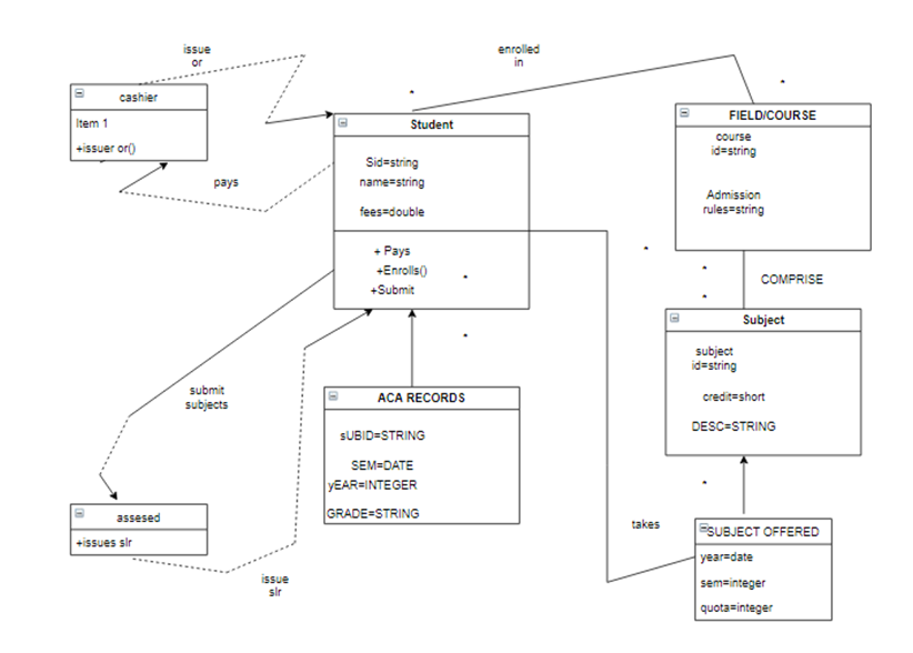
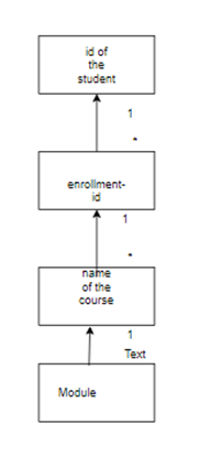
2. Class diagram defining the structure you want to use to represent the data in JSON.
The employment can be painstaking as an “associative type”, sometimes it is called the relation between the class that is answerable for model connections with method and distinctiveness. connect group are characteristically planned and reconstruct by means of the study.
Till present times, to my accepting at least there is no general programming source code which is promoting the plan of relations that need obligations. As we are going to form our software completely in this manner.
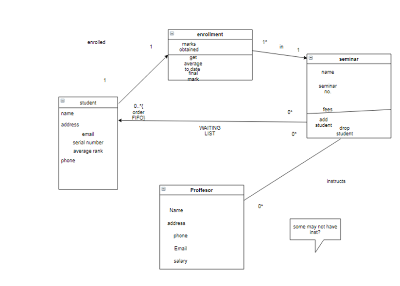
The explanation of the link was calculated. We could have insert a “ List for the waiting candidates name” attribute in the “seminar course” but favored to form it in a relation because it really does: the seminar artifacts hold zero or more items from the students wait list. Attributes and connections in UML 2.0 are the similar, hence they are essentially viewed as the same kind of stuff.
Figure 1: Mapping using JSON
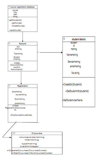
3.The JSON object
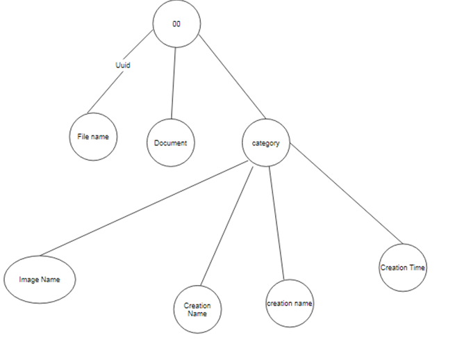
The following grades, as shown in figure, are done by means of transformation method.
(1) Udating Action belongs to the database of class named relation.
(2) “JSON Aysis” and “Aysis Read class”, “JSON read-object class” and model change class. (3)” Doc class” does type of data that model class has.
(4)Class name “ read”is the original class utilised for calling other classes including filling in all the file measures.
(5) The Account type is a goal configuration level, which displays get-and-getter for all characteristics. No description of other data models.
(6) The picture file output grade is FileOut that converts all binary data to JPG pictures.
Part B: XML – based on Part 2.1 – 4
We create the students.dtd file as below:
<?xml_version = “1.0”?>
<!–students.dtd-a document type definition for the students.xml–>
<!ELEMENT students (student+)>
<!ELEMENT student (name,address)>
<!ELEMENT name (first_name,last_name)>
<!ELEMENT firstname (#PC_DATA)>
<!ELEMENT lastname (#PC_DATA)>
<!ELEMENT address (street,city,email,phone)>
<!ELEMENT street (#PC_DATA)>
<!ELEMENT city (#PC_DATA)>
<!ELEMENT email (#PC_DATA)>
<!ELEMENT lastname (#PC_DATA)>
To use the DTD file, we must add this code into the XML file.
<!DOCTYPE students SYSTEM “students.dtd”>
students2.xml is completed in XML file.
<?xml version = “1.0”?>
<!– students2.xml for the DTD –>
<!DOCTYPE students SYSTEM “students.dtd”>
<students>
<student>
<name>
<first_name> Rosy </first_name>
<last_name> Peterson </last_name>
</name>
<address>
<street> 56 Elm Street</street>
<city> NY </city>
<email> [email protected] </email>
<phone> 4456790 </phone>
</address>
</student>
<student>
<name>
<first_name> Elena </first_name>
<last_name> Gilbert </last_name>
</name>
<address>
<street> 202 Dason Road </street>
<city> portsmorth </city>
<email> [email protected]</email>
<phone> 44088002 </phone>
</address>
</student>
</students>
7.Mapping from the class diagram
- Object Diagram
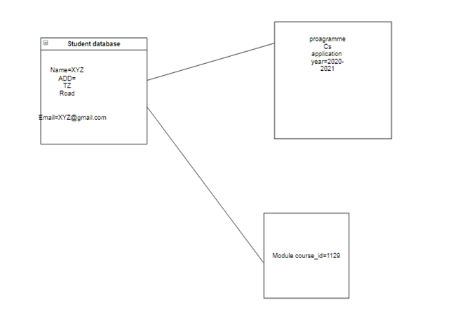
As we are aware of the fact that the “object diagram” explains the operation of the specific class occurrence are integrated at run-time, it consists of the same aspects at any moment as a “class diagram”, on the other hand contain classes and connections that demonstrate connections. But a small difference exists.
Part C: Data Integration – based on Part 3.2
1. Identifying conceptual overlaps
The technical wholeness, perseverance, suppleness, revival as well as an unplanned inquiry ability also is crucial features and distinctiveness of object-oriented databases. “Object-oriented database management systems” are following frameworks of structural decomposition of object-oriented analysis, layout and coding.
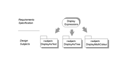
The technique recommended in this work is stimulated by concern with the “object oriented model” and thus, in places where the framework object-oriented is extended, the study is more significant. However, study into varied systems integrates many similarities in the areas of overlapping elements identification, conflict reconciliation in elements and system integration.
9.Explain it in a single sentence and say how you chose to resolve it in the integrated model.
In this case we have assigned parameters in the different variable so redundancy is removed.
Required Algorithm:
for all element “e” that is operated do
operation pre=null
for all operation p in operation list do
if p does not operate on then
continue inner iteration
else if p!=PO then
Pre:=null
else if pre=null then
pre := p
else
p: = combine and pre and p
pre : = p
}
end if
end for
end for

Greetings! Very helpful advice in this particular post! It’s the little changes that will make the largest changes. Many thanks for sharing!
https://twrd.in/TyUFeND
Way cool! Some very valid points! I appreciate you writing this article and also the rest of the site is also really good.
https://twrd.in/jAasxeh
https://ht.wpcookie.pro
Im grateful for the blog article.Thanks Again. Will read on…
https://undress.vip/
Muchos Gracias for your blog.Really thank you! Much obliged.
https://weiliandahome.com/collections/luxury-style
A big thank you for your post.Much thanks again. Keep writing.
https://caidenhnqvy.blogofchange.com/25128528/not-known-details-about-construction-company-in-nagpur
A big thank you for your blog article.Much thanks again. Fantastic.
https://bestbuildersinnagpur54208.designertoblog.com/56008156/about-best-builders-in-nagpur
Very informative blog article.Really looking forward to read more. Awesome.
https://chancegshpo.win-blog.com/4306311/technology-news-today-things-to-know-before-you-buy
Thanks again for the article.Much thanks again. Really Great.
https://zionrzdil.webdesign96.com/25185961/not-known-details-about-latest-technology-gadgets
I really liked your blog.Thanks Again. Will read on…
https://banjaramarketmirror62427.digitollblog.com/24800866/the-fact-about-banjara-market-mirror-that-no-one-is-suggesting
I appreciate you sharing this blog post.Thanks Again. Much obliged.
https://trekkingnearbangalore22850.blogdanica.com/24770049/trekking-near-bangalore-can-be-fun-for-anyone
Appreciate you sharing, great blog.Thanks Again. Really Cool.
https://zanderroiy00288.glifeblog.com/24732418/don-t-get-grounded-a-guide-to-renewing-your-80-97-115-115-112-111-114-116-32
Thanks for sharing, this is a fantastic blog article.Much thanks again. Awesome.
https://finnjvit65319.wikimeglio.com/8894013/down_under_dreams_unveiling_the_wonders_of_australia_for_tourists
I really liked your article post.Thanks Again. Really Cool.
https://edwinnwgov.blog5.net/66330682/5-simple-techniques-for-local-shifting-services
Really appreciate you sharing this blog.Thanks Again.
https://sethocqc09876.blogdon.net/explore-your-path-to-permanent-residency-in-canada-australia-and-beyond-40951023
Awesome post.Really looking forward to read more. Fantastic.
https://dungeonborne.com
Wow, great blog.Really thank you! Awesome.
https://dungeonborne.com
Thanks for sharing, this is a fantastic blog article.Really thank you! Great.
https://thefortuneslot.com/
A round of applause for your post.Thanks Again. Want more.
https://thefortuneslot.com/
Thanks for sharing, this is a fantastic blog.Really looking forward to read more. Want more.
https://www.3chlorine.com/
I appreciate you sharing this blog.Really thank you! Awesome.
https://www.3chlorine.com/
Very informative article post.Much thanks again. Great.
https://crushon.ai/
Really appreciate you sharing this article. Really Great.
https://crushon.ai/trends/ai_chat
Really enjoyed this article post.Really thank you! Awesome.
https://www.lianindustrial.com
Really informative article.Really thank you! Want more.
https://beckettlopn80235.wikidirective.com/6519664/the_advantage_of_nainital_hotels
I appreciate you sharing this post.Really thank you! Really Cool.
https://free-chatgpt.ai/
Awesome article post. Fantastic.
https://janitoraichat.com/zh
Thanks a lot for the article post.
https://www.us-machines.com/
Thanks for the article post. Keep writing.
https://www.us-machines.com/
Really enjoyed this post. Cool.
https://www.us-machines.com/
Thanks a lot for the article post. Really Great.
https://www.us-machines.com/
I really like and appreciate your blog article.Really looking forward to read more. Really Great.
https://free-chatgpt.ai/
I value the blog article.Really thank you! Really Cool.
https://crushon.ai/trends/nsfw_ai
Thanks so much for the article post.Really thank you! Keep writing.
https://www.panmin.com.es
Appreciate you sharing, great blog article.Really looking forward to read more. Much obliged.
https://www.panmin.com
wow, awesome article post. Keep writing.
https://www.hospital-xg.com
Muchos Gracias for your blog. Really Cool.
https://casinoplus.net.ph
Thanks for sharing, this is a fantastic blog post.Much thanks again. Want more.
https://crushon.ai/
Very neat blog.Really thank you! Really Great.
https://crushon.ai/character/503eeebe-1626-45bf-89e9-8614106dc5ab/details
Very good article.Thanks Again. Great.
https://crushon.ai/character/671a6a5f-5093-4846-b425-af7ce1589c24/chat
Thank you ever so for you article.Really thank you! Want more.
https://gpt-free.ai/
Im thankful for the blog.Really looking forward to read more. Awesome.
https://janitorai.chat/
Awesome post.Thanks Again. Much obliged.
https://mygenerator.ai/
Very informative article post.Thanks Again. Really Great.
https://crushon.ai/
Major thankies for the blog article. Want more.
https://crushon.ai/character/503eeebe-1626-45bf-89e9-8614106dc5ab/details
Thank you for your blog post.Thanks Again. Really Cool.
https://crushon.ai/character/f5757531-9a53-4c38-85ef-cd5ae51cdc13/details
wow, awesome blog article.Much thanks again. Really Cool.
https://crushon.ai/
Wow, great blog post.Thanks Again. Want more.
https://www.kubet.fyi/
Im obliged for the post.Really looking forward to read more. Great.
https://www.kubet.fyi/
Say, you got a nice blog.Really thank you! Great.
https://bonitocase.com/
Muchos Gracias for your blog post.Much thanks again.
https://bonitocase.com/
Very informative article post.Thanks Again. Will read on…
https://www.oneuedu.com/visa
I really enjoy the article.Thanks Again. Cool.
https://www.oneuedu.com/visa
A big thank you for your article post.Thanks Again. Will read on…
https://casinoplus.net.ph/
Major thanks for the blog.Really looking forward to read more. Great.
https://casinoplus.net.ph/
Muchos Gracias for your blog article.Really looking forward to read more. Keep writing.
https://chat.openai.com/g/g-u4cBExH7W-math-solver-ai
Thanks again for the article post.Really thank you! Really Great.
https://crushon.ai/
A big thank you for your blog post.Much thanks again. Fantastic.
https://crushon.ai/
I appreciate you sharing this article.Much thanks again. Really Great.
https://crushon.ai/
I really like and appreciate your blog article.Thanks Again. Fantastic.
https://crushon.ai/
Fantastic blog.Really thank you! Great.
https://talkietalkie.ai/
I value the article post.Thanks Again. Really Great.
https://crushon.ai/
Im grateful for the blog post. Awesome.
https://crushon.ai/character/83a80dbc-64e5-4b30-beda-7d42415f68e6/details
Thanks-a-mundo for the blog post.Really thank you! Keep writing.
https://chat.openai.com/g/g-A2YK8Gob6-pdf-ai-gpt-chat-pdf
Very informative post.Really looking forward to read more.
https://crushon.ai/
Very good post. Awesome.
https://callmeimei.com
Very good post.Really thank you! Really Great.
https://zhongli998.com
Really appreciate you sharing this post.Really thank you! Really Great.
https://zhongli998.com
Appreciate you sharing, great post. Really Great.
https://zhongli998.com
A round of applause for your blog.Much thanks again. Great.
https://www.temporary-fence.com.au
I think this is a real great blog post.Really looking forward to read more. Cool.
https://www.wiremeshfence.com
Thanks for sharing, this is a fantastic blog post. Great.
https://www.clearvufence.co.za
Great article post.Really thank you!
https://www.temporary-fence.com.au
Hey, thanks for the post. Great.
https://www.temporary-fence.com.au
I am so grateful for your article.Really thank you! Great.
https://www.wiremeshfence.com
Enjoyed every bit of your post.Really looking forward to read more. Much obliged.
https://animegenerator.ai/
Fantastic post.Really thank you! Keep writing.
https://fouadmods.net/
Thank you ever so for you post.Much thanks again. Fantastic.
https://fouadmods.net/
Thanks-a-mundo for the post.Much thanks again. Fantastic.
https://fouadmods.net/
Thanks for the blog.Much thanks again. Cool.
https://gbdownload.cc/
Hey, thanks for the article post.Thanks Again. Cool.
https://nsfwgenerator.ai/
I cannot thank you enough for the blog.Much thanks again. Really Cool.
https://chat.openai.com/g/g-0faZCnuDx-devin-ai
Really enjoyed this blog.Really thank you! Much obliged.
https://chat.openai.com/g/g-0faZCnuDx-devin-ai
Wow, great blog article. Fantastic.
https://www.yinraohair.com/human-hair/bundles
wow, awesome blog.Thanks Again. Much obliged.
https://www.yinraohair.com/cosplay/shop-by-color/blue
Thanks-a-mundo for the post.Thanks Again. Cool.
https://www.yinraohair.com/cosplay
Very neat article post. Much obliged.
https://simonhvhs65320.tinyblogging.com/paragliding-tips-68650355
Say, you got a nice blog article.Really thank you! Keep writing.
https://eduardosgtf20986.diowebhost.com/80312162/hvorfor-trenger-vi-rørleggerfirma
A round of applause for your blog post.Much thanks again. Really Cool.
https://danteereq64310.blogrelation.com/31376914/cpvc-pipe-manufacturers
Appreciate you sharing, great blog post.Thanks Again. Will read on…
https://dmozbookmark.com/story16817715/korean-skin-care-products-fundamentals-explained
I really liked your article post.Much thanks again. Much obliged.
https://travispdqc09765.aboutyoublog.com/26465612/home-appliances-products
I think this is a real great post.Much thanks again. Really Great.
https://www.secondcityhockey.com/users/wardrobesmanufacturers
Thanks again for the blog article.Thanks Again. Want more.
https://reallivesocial.com/story2221766/the-smart-trick-of-pest-control-service-in-anand-that-nobody-is-discussing
A big thank you for your blog article. Awesome.
https://topdirectory1.com/listings12677142/detailed-notes-on-toss-prediction