VEHICLE DYNAMICS
Executive Summary
The vehicle dynamics is a crucial factor in the field of automobile technology. This estimates the behaviour of the vehicle with respect to the ground or road or a solid surface. Now for the high-speed and high-performance vehicles like the race cars, the handling and ride quality is very important.
The high speed imposes large forces and impacts on the vehicle and the rider. So, the road-wheel contact is very important to be maintained. The paper has expressed the mathematical model needed for ensuring the wheel-road contact. Now the multi-model body analysis has shown the role of the variation of the native model from the mathematical system.

Hence a system of control using the “closed control system”. The results and discussion have shown how the coupling of feed-forward and feedback system gives better results than the feedback system. It has also opened the opportunity of practical applications of such a model.
The paper analysis has focused on the handling quality and the handling factor of the vehicle dynamics. For the handling of a racing car it is important to ensure the wheel-road contact. For that it is important to restrict the vertical motion of the wheelbase with respect to the ground.
The study will try to focus on that particular aspect of a chosen suspension system. It is taking help of kinematic analysis, computer aided modelling, multi-body modelling and mathematical models. The study will try to understand the optimal control solution regarding this aspect of the suspension system.
The aim of the paper or study is to design a suitable system for the suspension system to ensure the wheel-road contact. Thus the vertical wheel motion (displacement and the acceleration) needs to be nullified. So, the study will aim to implement a control system with the suspension system that will help this objective. So the objective of the study would be:
- To understand the Kinematics and dynamics of a suspension system using a mathematical model
- To understand the effect of the implementation of various control system configuration with the suspension (for road-wheel contact)
As per the discussion of Taghavifarand Mardani (2017), there are several factors that can possibly affect vehicle dynamics. The vehicle dynamics is the analysis of the effects of the driver inputs on the solid surface or ground. There are several factors that can possibly control this behaviour, such as:
- The power train
- The Braking system
- The steering geometry
- The track of axle
- Caster and camber angle
- Roll-centre
- Ride height
- Steering ratio
- Toe angle
- Scrub radius
- Wheelbase and the alignment of the wheel
- Suspension behaviour
- Moment of inertia
- Centre of mass
- Sprung and Unsprung mass
- Weight distribution etc.
These are some basic factors that are able to affect vehicle dynamics directly. There also some other factors like aerodynamics, aerodynamic drag, downforce, tire characteristics and load sensitivity etc.
There are various characteristics and behaviours that can attribute to the vehicle dynamics analysis. These factors are like the body flex and roll, pitch, yaw directional stability, ride quality, speed wobble, load and weight transfer, bump, rebound, steer quality etc (Jazar, 2017).
There are also other secondary parameters that are considered as the factors of the dynamics of the vehicle. These are like the noise, harshness, vibration and critical speed. Now, this analysis can be done using various methods such as a simple spring-mass system, a kinematic model or even a multi-body simulation system.
The multi-body system is a method of studying the dynamics of an interconnected system of flexible and rigid systems. Each body or object in the system can undergo even large rotational or translational motion. Yet the entire system will be subjected to a fixed “Degree of Freedom”.
Each element is to be analyzed using the Newtonian (free particle-based) and Eulerian (rigid body-based) system of analysis. In the Eulerian analysis, the reaction forces are to be incorporated into the analysis (Linget al. 2018). The Lagrangian formalism has implemented a series of equation evaluation to understand the behaviour along with the constraints.
Now, the application of the vehicle dynamic here is to be implemented in the racing car dynamics of ride and handling. The factor that is aimed to be analyzed here is the effects of the suspension system, according to the study of Dumitruet al. (2016), the importance of the suspension system of a vehicle dynamics regarding the wheel-road contact.
The ride quality and the handling are dependent on the contact of the wheel with the road. So, the vertical motion of the wheelbase needs to the zero with respect to the ground.
Based on the suspension system for the analysis, an open-wheel design can be used for the system description.
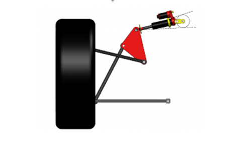
Figure 1: The Suspension System Description
(Source: Deet al. 2017)
The primary features of the system of suspension are “double-wishbone layout” and “shock-absorber actuated”. A push-rod is connected to the “lower wishbone”, and a mechanical link is placed between the chassis and the shock-absorber. The link can be actuated using a servo-motor that will help to vary the mechanical link angle (Deet al. 2017).
This will help to change the damper and spring orientation in the suspension system. By changing the angle of inclination the impact of the damping and the elastic force can be varied thus.
A preliminary study needs to be done using the Kinematic analysis top, realizing the suspension geometry of the model. Software like LSA can help to verify the performance in terms of the Kinematics. Thus the exact dimensions can be evaluated to model a CAD model for the system like SolidWorks.
The Kinematics is a field of mechanics where the motion of bodies, points (simplified) and body systems is analyzed without considering the external forces. In the Kinematic analysis process, the kinematic quantities are measured to define the motion.
In this study, the Kinematic Analysis process is focused on designing the mechanism for a specified range of movement or motion (Pradhan, and Samantaray, 2018). The Computer-Aided Design method will then be implemented using CAD software to develop the digital 3D prototype.
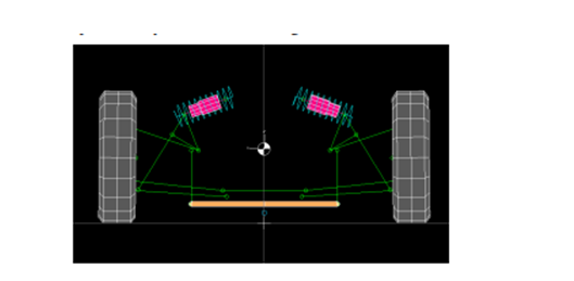
Figure 2: Kinematic simulation using LSA
(Source: Deet al. 2017)
It is to be remembered that the effects of the roll centre height and the camber angle on the rebound and bump are considered. The height should not be negative, and the motion ratio and the toe angles are evaluated from these factors. [Referred to Appendix 1]
The mathematical model will help to understand the optimal motion law. The optimal motion describes the motion of the system using optimal control. So, it will be helpful to understand the vehicle dynamics of handling in terms of the suspension systems (Marzbaniet al. 2019).
Here the optimal motion is to be understood for the two cranks using a simplified model with a unit degree of freedom (DOF).
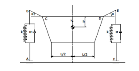
Figure 3: Simplified Physical model
(Source: Deet al. 2017)
For the mathematical model, Lagrange’s equation is to be used:
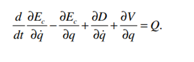
Figure 4: Lagrange’s Equation of motion
(Source: Deet al. 2017)
Here, Ec = Kinetic energy of the system
D = dissipated power (by damping)
Q = “Generalized External Forced Vector.”
From this differential equation of motion using the DOF as unity or one, we get a non-linear equation:
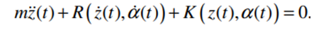
Figure 5: Non-linear equation of motion for unit DOF
(Source: Deet al. 2017)
Here, m = translating mass
R = damping force
z = vertical displacement
= vertical velocity
α = angular position
= rotational velocity
The road profile can be estimated with a sine wave function (L = wavelength, T = time period and Y = amplitude)
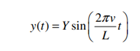
Figure 6: Road profile sine-wave function
(Source: Deet al. 2017)
Here, v = the velocity
The next considering will be the “vertical position of the suspension lower ends” with respect to the ground, which is zA and zF (say). Thus the angular position and the angular velocity for the cranks can be estimated from the model. These are:
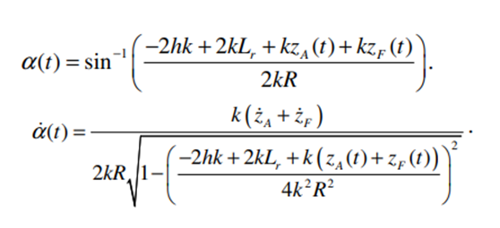
Figure 7: Simplified Physical model
(Source: Deet al. 2017)
From these models, the motion model and Kinematics can be well understood. These factors for both the cranks will help to counteract the forces produced for the vertical motions (of F and A point). This will be the criteria to be put in the multi-body model. [Referred to Appendix 2]
The results for the evaluation of the semi-active system the Multi-body model is crucial for the half-car model. The emphasis is important to get as much possible behaviour as possible to gain. The linear actuators are attached to the wheel bottom (for measuring zA and zF).
The chassis is not the centre of focus and can be neglected for the study. The wheels are to be given the ability to get detached from the actuators but needs to be constrained from any negative vertical motion (Jacobson, 2016). This will allow for more practical modelling of the system. In order to get an optimal relation, a “closed-loop control system” is required to be incorporated into the system.
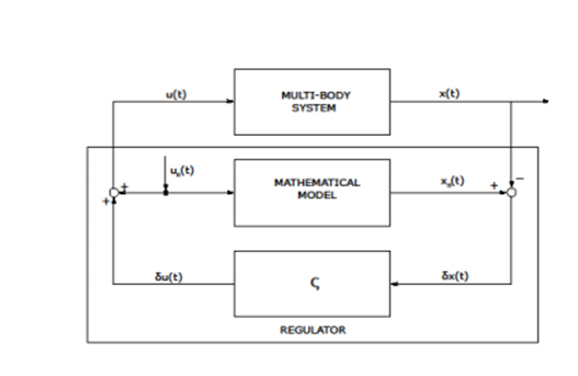
Figure 8: Closed-loop control
(Source: Deet al. 2017)
The regulator will receive “δx(t)” which is the deviation of the model from the mathematical model. Also, it will produce “δu(t)” as output which is the closed-loop feedback control input. Also, the application of the feed-forward control law in order to minimize the variation is made with the aid of PID control.
Here the deviation is basically the actual vertical displacement of the wheels as they are estimated to be zero (Shiet al. 2018). The mechanical link actuator is to be used for implementing the control system into the mechanism.
So, there are two patterns to be observed in the results, which are:
- The results for the original or native (passive) system
- The results for feed-forward control (FFW)
- The results of the combined effects of feedback control (FB) and feed-forward control (FFW)
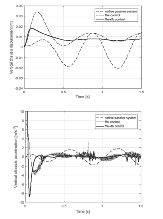
Figure 9: The vertical displacement and acceleration for each system
(Source: Deet al. 2017)
For the displacement, the various steady-state measurements are dependent on the various configurations for the mechanical link. The configurations are responsible for changing the ride height of the system.
From the displacement results, it is clearly observable how the FB system helps to dampen the oscillation amplitude. But it is also visible that due to the differences or variations of the mathematical model and the multi-body model, the zero amplitude is not possible to reach.
But whenever the FFW system is coupled along with the FB system, the amplitude is nullified. Also, for the acceleration analysis, a reduction in the amplitude is observable as compared to the passive original or native system.The accurate analytic model preparation has been the motive of the study, which is quite achievable using the coupled system.
The two factors that were influential here are the identification of the numeric parameters and the optimization using the optimal control. For this, the implementation of Lagrange’s model was effective. This yielded a set of equations for the motion that was the mathematical model for the dynamic analysis.
Then the model helped to understand the numeric parameters to be checked (the vertical motion parameters). But before that, it was important to incorporate a Kinetic analysis to understand the dimensions and operating characteristics of the suspension system. This was the basis of the entire system of dynamic vehicle analysis on the suspension system.
So, in the field of vehicle dynamics the use of multi-body modelling with collaboration with the mathematical models is really helpful. The modelling of the design with proper multi-body components are able to help implement the required constraints in proper place.
Also, the mathematical models help to understand the theoretical model of these constraints. For instance, here the vertical motion (displacement and acceleration) is the constraint that is to be restricted. Thus the kinematic analysis can be realized using a digital prototype only without wasting physical materials.
The aim of the study is to understand the vehicle dynamics regarding the suspension system. So, the mathematical model has regarded the vertical motion of the wheelbases to be zero. But the variation of the multi-body model causes wheel-road detachment.
So, an optimal control system was to be considered. Firstly only the feedback control was analyzed, and then a coupled system of the feedback with the feed-forward system was analyzed. The results have shown that though the FB system reduces or dampens the variation, only the “FFW+FB” was able to nullify the variation.
A physical parameters testing, if done on physical models, requires repetitive prototyping and testing. Thus a substantial amount of physical materials, time, money and efforts get wasted. But the computer based modelling helps to eliminate these wastages. For the kinematic analysis implementation of the multi-body model along with a feasible mathematical model made this job feasible and easier.
Book
Jazar, R.N., 2017. Vehicle dynamics: theory and application. Springer.
Journals
De, S., Rivera, Z.B. and Guida, D., 2017. A new semi-active suspension system for racing vehicles. FME Transactions, 45(4), pp.578-584.
Taghavifar, H. and Mardani, A., 2017. Off-road vehicle dynamics. Studies in Systems, Decision and Control, 70, p.37.
Dumitru, A., Preda, I. and Mogan, G., 2016. Aspects Concerning Modeling and Simulation of a Car Suspension with Multi-Body Dynamics and Finite Element Analysis Software Packages.
Ling, L., Zhang, Q., Xiao, X., Wen, Z. and Jin, X., 2018. Integration of car-body flexibility into train–track coupling system dynamics analysis. Vehicle System Dynamics, 56(4), pp.485-505.
Pradhan, S. and Samantaray, A.K., 2018. Integrated modeling and simulation of vehicle and human multi-body dynamics for comfort assessment in railway vehicles. Journal of Mechanical Science and Technology, 32(1), pp.109-119.
Kissai, M., Monsuez, B. and Tapus, A., 2017, September. Review of integrated vehicle dynamics control architectures. In 2017 European Conference on Mobile Robots (ECMR) (pp. 1-8). IEEE.
Marzbani, H., Khayyam, H., To, C.N., Quoc, Đ.V. and Jazar, R.N., 2019. Autonomous vehicles: Autodriver algorithm and vehicle dynamics. IEEE Transactions on Vehicular Technology, 68(4), pp.3201-3211.
Jacobson, B., 2016. Vehicle dynamics. Chalmers University of Technology.
Cui, L., Hu, J., Park, B.B. and Bujanovic, P., 2018. Development of a simulation platform for safety impact analysis considering vehicle dynamics, sensor errors, and communication latencies: Assessing cooperative adaptive cruise control under cyber attack. Transportation research part C: emerging technologies, 97, pp.1-22.
Shi, H., Wang, J., Wu, P., Song, C. and Teng, W., 2018. Field measurements of the evolution of wheel wear and vehicle dynamics for high-speed trains. Vehicle System Dynamics, 56(8), pp.1187-1206.
Website
jstor.org, (2020), Dynamics of Vehicle Suspensions Available at: https://www.jstor.org/stable/44579831?seq=1#metadata_info_tab_contents [Accessed on 10.07.2020]
Appendix 1: Effects of roll centre height and camber angle on the rebound and bump
(Source: Deet al. 2017)
Appendix 2: Vertical displacement and acceleration model for DOF = 1
(Source: Deet al. 2017)

https://meclizinex.com/
antivert
generic cialis online fast shipping http://tadalafilise.cyou/# cost of cialis
tadalafil drug http://tadalafilise.cyou/# tadalafil price walmart
cialis professional 20 mg pills tadalafilise.cyou/#